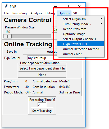
If you have the High LED power version of PiVR you must take
care to properly shield yourself and others from the potentially
very strong LED light to protect eyes and skin!
Important
Several options will open a pop-up. You must close the pop-up in
order to interact with the main window.
Important
The software has different functionality if run on a Raspberry Pi
as compared to any other PC. This software manual is for the
Raspberry Pi version of the software
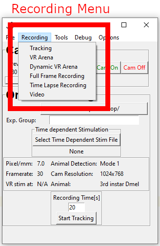
The Recording Menu lets you choose between different recording
options. There are currently 4 different methods:
Tracking – Online tracking of a single animal. Possibility of
delivering a time dependent stimulus.
VR Arena – Online tracking of a single animal. Present a
virtual arena that will define how the stimulus is present in
response to the position of the animal.
Dynamica VR Arena - Online tracking of a single animal. Present
a virtual arena as above but which changes over time.
Full Frame Recording – Record an image sequence. Possibility
of delivering a time dependent stimulus.
Timelapse Recording - Record a long image sequence at low
frequency.
Video – Record a video (h264 format). Possibility of
delivering a time dependent stimulus.
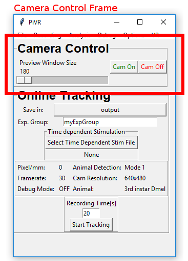
In all of the recording options you have access to the Camera control
frame. It can be used to turn the camera preview on (Cam On) and off
(Cam Off). You can also control the size of the preview window.
Warning
The Camera preview is always on top of everything else on the
screen. Use the Preview Window carefully!
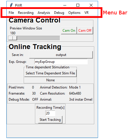
The ‘Recording’ Option you choose is printed in bold on top of the
Experiment Control Frame. In this example it is ‘Online Tracking’.
Online tracking tracks a single animal.
You have to select a folder in which the experiment will be saved by
clicking on the button to the right of ‘Save in:’.
You can then give your experiment an identifier. Examples include
genotypes or an experimental treatment. This information will be
saved in your experiment folder.
If you want to present a Time Dependent Stimulus you can press the
button ‘Select Time Dependent Stim File’. Please make sure you follow
the guidelines to learn how to prepare
the file.
The figure below gives you a quick overview over of the parameters used
by the program:
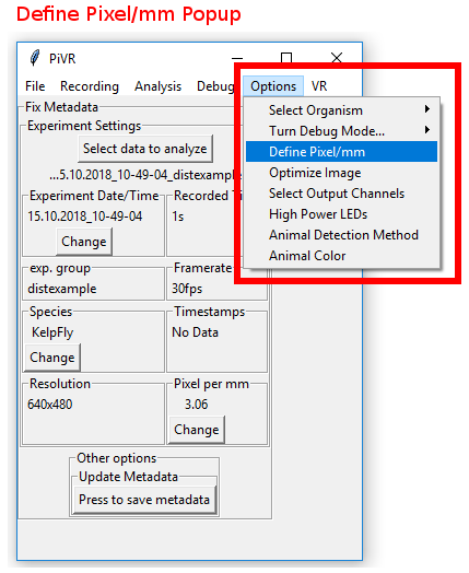
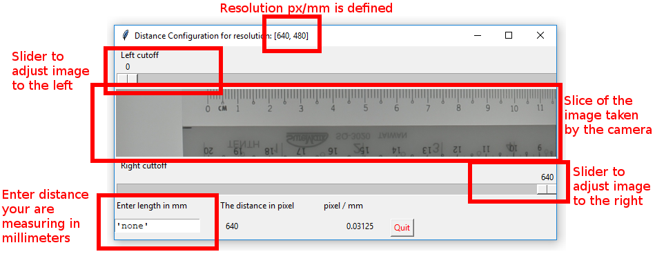
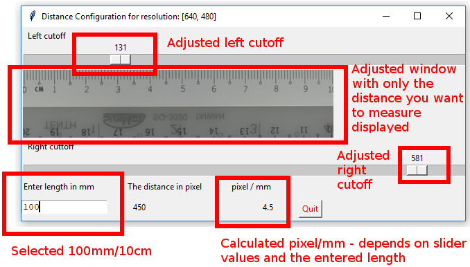
Pixel/mm: Essential: This value has to be set by you
before you run your first experiment! See set
Pixel/mm. You must change it after changing the
resolution or adjusting the height of the camera relative to the
arena!
Frame rate: The frame rate you will be using to track the animal. See
adjust image to see how to adjust
the frame rate.
Warning
There is a difference between the frame rate the camera
can deliver and the frame rate the Raspberry Pi can handle. If
you select a very high frame rate you might get a
lower frame rate than expected. Always check the
timestamps in the ‘data.csv’ if you are trying a new,
higher frame rate than before!
Cam Resolution: Indicates the resolution you selected. See
adjust image to see how to change
the resolution.
Important
Online Tracking has only been tested
with the following resolutions: 640x480, 1024x768, 1296x972.
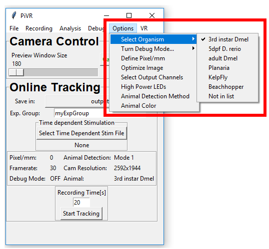
Animal: Essential: for Online Tracking. See here for
how to select an animal. See Define new
animal in case you are working with an
animal which is not listed. If you are having problems detecting
your animal see here.
Next, enter the time you want to track the animal in the field
below ‘Recording Time[s]’. Then hit ‘Start Tracking’.
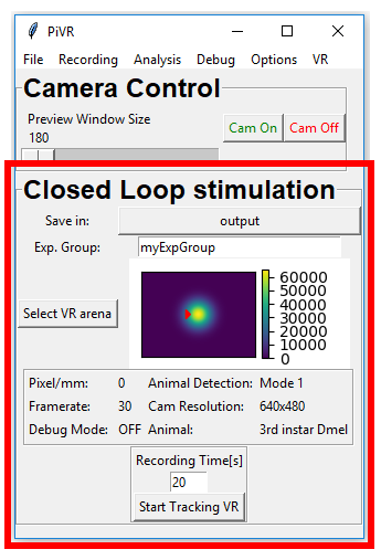
The ‘Recording’ Option you choose is printed in bold on top of the
Experiment Control Frame. In this example it is ‘Closed Loop
Stimulation’.
Closed Loop Stimulation tracks a single animal.
You have to select a folder in which the experiment will be saved by
clicking on the button to the right of ‘Save in:’.
You can then give your experiment an identifier. Examples include
genotypes or an experimental treatment. This information will be
saved in your experiment folder.
To present a virtual arena (stimulation depending on the position of
the animal) press the ‘Select VR Arena’ button and select an arena.
Static virtual arenas are csv files. Note that you can present the
virtual arena either at a fixed position and independent of the
starting position of the animal (e.g. file “640x480_checkerboard.csv”)
or you can have the position of the arena defined by the starting
position of the animal (e.g. file
“640x480_gaussian_centred_animal_pos[250, 240,0.0].csv”). See
here for an in-depth explanation.
The figure below gives you a quick overview of the parameters used by
the program:
Pixel/mm: Essential: This value has to be set by you
before you run your first experiment! See set Pixel/mm. You must change it after changing the resolution
or adjusting the height of the camera relative to the arena!
Frame rate: The frame rate you will be using to track the
animal. See adjust image to see how
to adjust frame rate.
Warning
There is a difference between the frame rate the camera can
deliver and the frame rate the Raspberry Pi can handle. If you
select a very high frame rate you might get a lower frame rate
than expected. Always check the timestamps in the ‘data.csv’
if you are trying a new, higher frame rate than before!
VR stim at: Either Head, Centroid, Midpoint or Tail. See
here how to turn it on.
Cam Resolution: Indicates the resolution you selected. See
adjust image to see how to change
the resolution.
Animal: Essential: for Closed Loop Experiments. See here for how to
select an animal. See Define new
animal in case you are working with an
animal which is not listed. If you are having problems detecting
your animal see here
Next, please enter the time you want to track the animal in the field
below ‘Recording Time[s]’. Then hit ‘Start Tracking VR’.
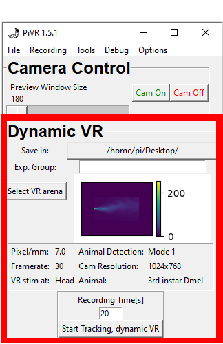
The ‘Recording’ Option you choose is printed in bold on top of the
Experiment Control Frame. In this example it is ‘Dynamic VR’.
Dynamic VR tracks a single animal.
You have to select a folder in which the experiment will be saved by
clicking on the button to the right of ‘Save in:’.
You can then give your experiment an identifier. Examples include
genotypes or an experimental treatment. This information will be
saved in your experiment folder.
To present a dynamic virtual arena (stimulation depending on the
position of the animal) press the ‘Select VR Arena’ button and select
an arena.
Dynamic virtual arenas are npy files. See
here for an in-depth explanation and
how to create them.
The figure below gives you a quick overview of the parameters used by
the program:
Pixel/mm: Essential: This value has to be set by you
before you run your first experiment! See set Pixel/mm. You must change it after changing the resolution
or the adjusting height of the camera relative to the arena!
Frame rate: The frame rate you will be using to track the
animal. See adjust image to see how
to adjust the frame rate.
Warning
There is a difference between the frame rate the camera can
deliver and the frame rate the Raspberry Pi can handle. If you
select a very high frame rate you might get a lower frame rate
than expected. Always check the timestamps in the ‘data.csv’
if you are trying a new, higher frame rate than before!
VR stim at: Either Head, Centroid, Midpoint or Tail. See
here how to turn it on.
Cam Resolution: Indicates the resolution you selected. See
adjust image to see how to change
the resolution.
Animal: Essential: for Closed Loop Experiments. See here for how to
select an animal. See Define new
animal in case you are working with an
animal which is not listed. If you are having problems detecting
your animal see here.
Next, enter the time you want to track the animal in the field
below ‘Recording Time[s]’. Then hit ‘Start Tracking, dynamic VR’
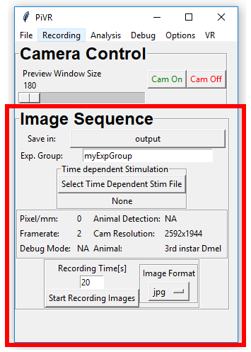
5.2.5. Experiment Control Frame – Full Frame Recording
The ‘Recording’ Option you choose is printed in bold on top of the
Experiment Control Frame. In this example it is ‘Image Sequence’.
Image Sequence just records still images without tracking anything.
The advantage over video is that no compression of the image data is
done. The disadvantage is that it is limited by the time it takes the
Raspberry Pi to write the file on the SD card. If you are using a
higher quality SD card, you will be able to write at a higher
frame rate. However, it will probably always be lower than video.
You have to select a folder in which the experiment will be saved by
clicking on the button to the right of ‘Save in:’.
You can then give your experiment an identifier. Examples include
genotypes or an experimental treatment. This information will be
saved in your experiment folder.
If you want to present a Time Dependent Stimulus you can press the
button ‘Select Time Dependent Stim File’. Please make sure you follow
the guidelines to learn how to prepare
the file.
The figure below gives you a quick overview of the parameters used by
the program:
Pixel/mm: This value indicates how many pixels are in one mm.
You will need this value to be correct to calculate anything
with distance afterwards (speed, distance to source etc.) See
set Pixel/mm. You must change it after
changing the resolution or adjusting the height of the camera
relative to the arena!
Frame rate: The frame rate at which you will be collecting images. See
adjust image to see how to adjust
the frame rate.
Warning
There is a difference between the framerate the camera
can deliver and the framerate the Raspberry Pi can handle.
If you select a very high framerate you might get a lower
framerate than expected. Always check the timestamps in
the ‘data.csv’ if you are trying a new, higher framerate
than before!
VR stim at: N/A.
Animal Detection Mode: N/A.
Cam Resolution: Indicates the resolution you selected. See
adjust image to see how to change
the resolution.
Animal: Value that will be saved in ‘experiment_settings.json’.
Select the image format you want your images to be in: jpg, png, rbg,
yuv or rgba. See here for details
on the different formats.
Next, please enter the time you want to track the animal in the field
below ‘Recording Time[s]’.
Then hit ‘Start Recording Images’.
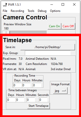
5.2.6. Experiment Control Frame – Timelapse Recording
The ‘Recording’ Option you choose is printed in bold on top of the
Experiment Control Frame. In this example it is ‘Timelapse’.
Timelapse is similar to ‘Image Sequence’ (See above) in that it
records still images without tracking anything.
In contrast to ‘Image Sequence’, it allows the taking of pictures at
less than 2 frames per second, the minimal frame rate for all other
modes.
You have to select a folder in which the experiment will be saved by
clicking on the button to the right of ‘Save in:’.
You can then give your experiment an identifier. Examples include
genotypes or an experimental treatment. This information will be
saved in your experiment folder.
Note
Please open a ticket on gitlab
if you want to be able to present a time dependent stimulus.
The figure below gives you a quick overview of the parameters used by
the program:
Pixel/mm: This value indicates how many pixels are in one mm.
You will need this value to be correct to calculate anything
with distance afterwards (speed, distance to source etc.) See
set Pixel/mm. You should change it after
changing the resolution or adjusting the height of the camera
relative to the arena!
Frame rate: The frame rate the camera is running.
VR stim at: N/A.
Animal Detection Mode: N/A.
Cam Resolution: Indicates the resolution you selected. See
adjust image to see how to change
the resolution.
Animal: Value that will be saved in ‘experiment_settings.json’.
In Recording Time indicate the total time you wish to record.
In ‘Time between Images’ enter the time between frames.
Warning
You must make sure that enough space remains on the Raspberry
Pi. If you run out of space, the program will most likely throw
an error and stop recording.
Select the image format you want your images to be in: jpg, png, rbg,
yuv or rgba. See here for details
on the different formats.
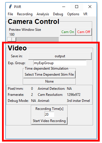
The ‘Recording’ Option you choose is printed in bold on top of the
Experiment Control Frame. In this example it is ‘Video’.
As the name indicates, use this option to record videos. The
advantage of this method over image sequence is its superior speed.
Since v1.8.0 another advantage is the possibility of using
macros.
The disadvantage, especially for scientific questions, might be that
it compresses the image file in the temporal domain. See here
for an introduction and the Wikipedia page for more details.
If not using the macro editor (see here
for more information), you have to select a folder in which the
experiment will be saved by clicking on the button to the right of
‘Save in:’.
You can then give your experiment an identifier. Examples include
genotypes or an experimental treatment. This information will be
saved in your experiment folder.
If you want to present a Time Dependent Stimulus you can press the
button ‘Select Time Dependent Stim File’. Please make sure you follow
the guidelines to learn how to prepare
the file.
The box below gives you a quick overview over the parameters used by
the program:
Pixel/mm: This value indicates how many pixels are in one mm.
You will need this value to be correct to calculate anything
with distance afterwards (speed, distance to source etc.) See
set Pixel/mm. You must change it after
changing the resolution or adjusting the height of the camera
relative to the arena!
Frame rate: The frame rate at which you will be recording the video. See
adjust image to see how to adjust
the framerate.
Warning
There is a difference between the frame rate the camera
can deliver and the frame rate the Raspberry Pi can handle.
If you select a very high frame rate you might get a lower
frame rate than expected. Always check the timestamps in
the ‘data.csv’ if you are trying a new, higher frame rate
than before!
VR stim at: N/A.
Animal Detection Mode: N/A.
Cam Resolution: Indicates the resolution you selected. See
adjust image to see how
to change the resolution.
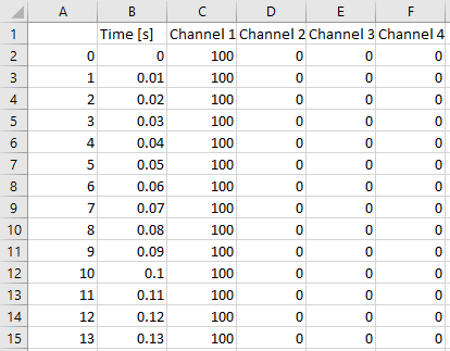
In your PiVR folder you can find a folder called
‘time_dependent_stim’. On a fresh install it is supposed to contain a
single file: blueprint_stim_file.csv.
When you open it with, e.g. excel or your csv viewing program of
choice, you’ll see that there are 6 columns and many rows:
The first column (A) is just an index and not really important. The
second column (B) indicates the time at which the stimulus defined
in the columns labelled ‘Channel 1’, ‘Channel 2’, ‘Channel 3’ and
‘Channel 4’ is being presented. See here what
a ‘Channel’ is.
0 means the light is completely OFF. 100 means the light is completely
ON. A number in between, e.g. 50, means that the light is on at
50/100=50%.
You may use the provided file as a blueprint to create your own
stimulus by adding the stimulus intensity at the desired timepoint.
Note that the stimulus must be between 0 and 100.
Alternatively, you can create another file from
scratch. It is important that the file is a csv file with the identical
column names as provided in the file above.
You can change the time resolution if you wish.
Important
What is a good time resolution to program into the time dependent
stimulus file? It depends:
Internally, PiVR keeps track of time using timestamps from the
camera.
It then calls numpy.searchsorted
on the provided ‘Time [s]’ column.
The algorithm is fast but at a low time resolution can lead to
unexpected results as it will always stop whenever it finds a value
larger than the one it looks for.
For example, if you provide one timepoint for each second while
recording at 10 frames per second for the first frame at t=0 it will
present the stimulus for t=0. At t=0.1s it will already provide
stimulus defined at 1second.
A good compromise between precision and file size for e.g. 10 frames
per second is a resolution of 0.01 seconds (10ms). If you want to
use higher frame rates AND you need very precise stimuli you should
increase the resolution to 0.001 seconds (1ms). Anything above is not
useful considering that PiVR can’t run at frequencies above 90 Hz
(about 10ms per frame).
Note
Before v1.7.0, Time Dependent Stimulus File was defined based on
frame. The above was implemented to give better control over when
exactly a stimulus is presented. The previous method could introduce
incoherence between experiments and it is therefore strongly recommended to
use the method described above.
If you must use the frame based Time Dependent Stimulus File you may
find more information here.
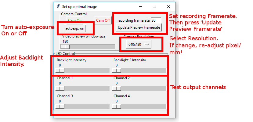
Make sure the autoexposure button says ‘autoexp on’.
Turn the Backlight Intensity up. It is normal to only see
something above 150’000. 400’000-500’000
is often a good value to choose.
If you have Backlight 2 intensity on one of the GPIOs (see
define GPIO output channels) you can
also adjust Backlight 2 intensity at this point.
To test your output channels, slide the appropriate slider to
the right. At the beginning of any experiments, these will be
turned off again. To keep a stimulus ON for the duration of the
experiment use the Backlight 2 intensity.
In order to set up optimal image parameters I usually do the following:
Turn ‘Cam On’.
Set ‘autoexp on’.
Pull ‘Backlight Intensity’ slider all the way to the left
(Image will be dark).
Now pull the ‘Backlight Intensity’ slider to the right. As
soon as I see an image in the camera I go another 100’000 to
the right - this way I’m not at the lower detection limit of the camera.
Then I turn ‘autoexp off’.
Often it can improve the image if I pull the ‘Backlight
Intensity’ slider a bit more to the right, effectively
overexposing the image a bit.
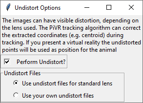
In v1.7.0, the undistort feature was added. See
here (Gitlab) or
here (PiVR.org) to see a
detailed explanation of what the problem is and how PiVR is solving it.
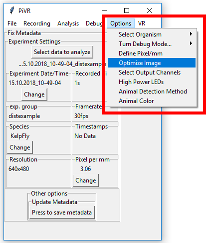
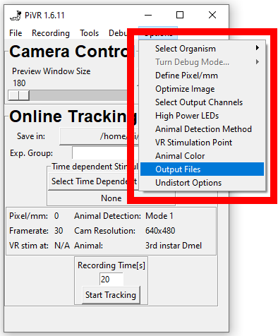
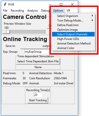
To find the menu, press the ‘Options’ menu in the Menu Bar. Then select
‘Undistort Options’.
Note
This option cannot be turned on if opencv is not installed. If
the menu is greyed out make sure to install opencv. In addition,
you will have ‘noCV2’ written next to the version number of PiVR.
If you are on the Raspberry Pi the easiest way to install opencv
is to wipe the SD card, reinstall the OS and make a clean install
of the PiVR software using the installation file.
On a PC, just install it using conda by first (1) activating the
PiVR environment and (2) entering conda install -c conda-forge opencv
In this menu you can choose to perform undistort during tracking or not.
If you are not using the standard lens that comes with the camera
in the BOM you need to use your own undistort files.
What happens with the virtual reality when using undistort? Nothing, actually:
Undistort ensures equal spacing between each pixel no matter the position
on the field of view on the camera (and the lens which causes distortion in the
first place).
However, there’s a discrepancy between what a user sees in the preview vs. what is
actually happening: The preview window shows the distorted image and the VR arena.
In reality (and when using undistort), the position of the animal in the VR arena is
not exactly at the position shown in the preview window. This becomes most
obvious when using a checkerboard VR arena with sharp boundaries.
There will also be positions in the VR arena which are impossible for the animal to
occupy, as shown in the image here:
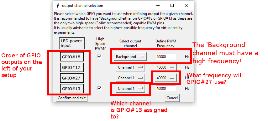
There are 4 GPIO’s that can be used to control LEDs: GPIO#18,
GPIO#17, GPIO#27 and GPIO#13. (Side Note: GPIO#18 and
GPIO#13 are special as they are the only ones that are capable of
providing PWM frequencies above 40kHz.)
To give the user maximum flexibility, each of the GPIO’s can be
assigned a ‘Channel’ which can be controlled independently in the
software. This also allows the ‘bundling’ of GPIO’s into Channels.
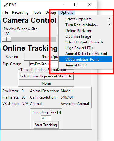
In order to define GPIO output channels for your resolution, press
the ‘Options’ menu in the Menu Bar. Then select ‘define GPIO output
channels’.
The images on the far left indicate which of the outputs on the left
of your setups are which GPIO (e.g. the one closest to the LED power
input is GPIO#18).
Channel 1 is always defined as the channel that is used for the
Virtual Arena experiments.
Channel 1, Channel 2, Channel 3 and Channel 4 can be separately
addressed using the time dependent stimulus files.
The standard frequency values are set for the normal PiVR setup
running exclusively with LED strips:
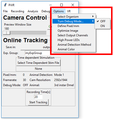
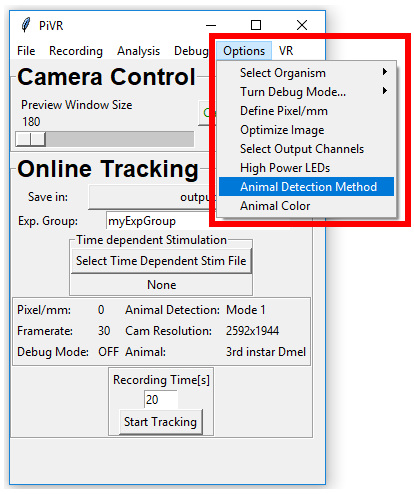
In order define the animal detection method press ‘Options’ menu in
the Menu Bar. Then press ‘Animal Detection Method’.
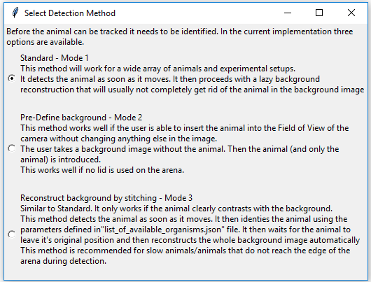
When in either ‘Online Tracking’ or ‘Closed Loop Stimulation’ the
animal needs to be detected. There are 3 modes that can be used to
detect the animal. For most cases Mode 1 (Standard) will be fine. If
you need a clear background image consider Mode 2 or Mode 3.
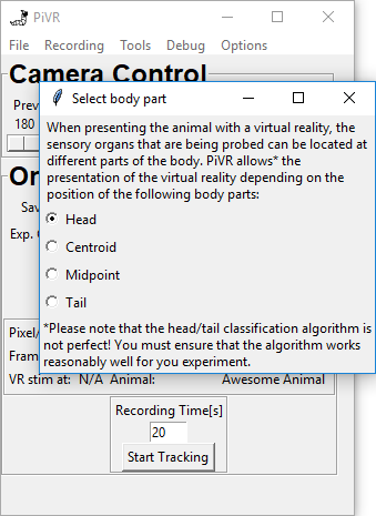
When running virtual reality experiments the cells you are interested
in could be at different places of the animal.
PiVR allows you to present the virtual reality depending on
different body parts identified during
tracking.
You may choose different body parts that are defined during tracking.
Note
As the difference between centroid and midpoint is not
straightforward, please see here for an
explanation.
The Head (standard) will probably make a lot of sense in many
experiments, as a lot of sensory neurons of many animals are
located there. However, be aware that the Head/Tail classification
algorithm is not perfect and does make mistakes. There is no
option to correct for wrong head/tail assignment during the
experiment!
The Centroid is probably the most consistently correct point
during tracking. Please see
here to see how it is defined.
The Midpoint is similar to the centroid, but can be different in
flexible animals such as fruit fly larvae.
The tail is the final option to choose from. We have used the
presentation of the virtual reality based on tail position as a
control in the past.
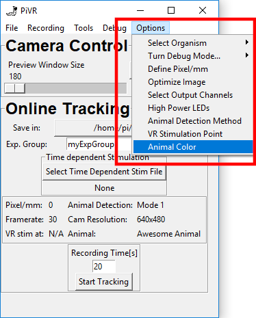
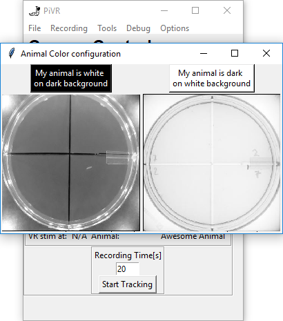
Depending on your experimental setup, the animal can either be dark
on white background due to transillumination, or white on dark
background due to side illumination.
The standard setting is dark on white. If you need to change this
setting, go to Options->Animal Color.
Now just press the button above the image that describes your
experiment.
When having multiple PiVR setups it’s a good idea to keep track of where
a given experiment is coming from. With v1.8.0 a setup has the standard
name ‘myPiVR-init_DATE’ with DATE indicating the date the Raspberry Pi showed
when the PiVR software was started for the first time (or for older setups, when
they were updated to v1.8.0).
The setup name is written to the ‘experiment_settings.json’ file for each experiment
and it might be helpful for you to give a custom name such as ‘DoorSetup’ to indicate the
setup closet to the door, for example.
To change the name , Go to Options->Setup Name:
Enter whatever name you wish and press ‘confirm and exit’:
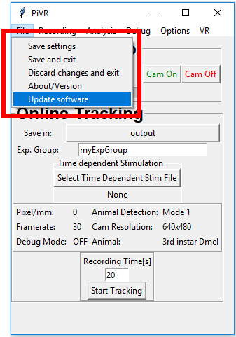
Save settings by going to ‘File->Save and Exit’ and restart the PiVR
software. Now the custom name you gave the setup is indicated next to
the version number: