PiVR has been developed by David Tadres and Matthieu Louis (Louis Lab).
1. Build your own PiVR
It doesn’t take long and it isn’t too hard to build PiVR. See this timelapse video where a PiVR setup is being 3D printed, the Printed Circuit Board (PCB) soldered and then built.
1.1. Standard and High Powered version
PiVR comes in two versions:
The Standard version: LED strips are used for both the backlight and stimulation light. We have measured around \(2{\mu}W/mm^2\) for red light intensity and around \(8000 Lux\) when measuring white light intensity. Please see the Bill of Materials for components you must buy to build the setup.
The High Powered Version: The stronger LEDs require not only a different arena but also dedicated LED drivers which provide a constant current. We have measured light intensities in the order of \(40 - 50{\mu}W/mm^2\) for the red LEDs. Please see Bill of Materials for components you must buy to build the setup. Note that there are a few limitations compared to the standard version regarding the available dynamic range and the available precision.
See the following list for the main differences which might help you choose the best setup for your needs.
Standard Setup |
HP Setup |
|
|---|---|---|
Price |
~415USD |
~610USD |
Max. light intensity |
\(2{\mu}W/mm^2\) |
\(40 - 50{\mu}W/mm^2\) |
LED Control |
100% of possible light intensities 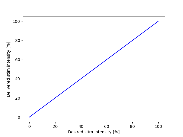
|
Only 5-98% of possible light intensities useable. 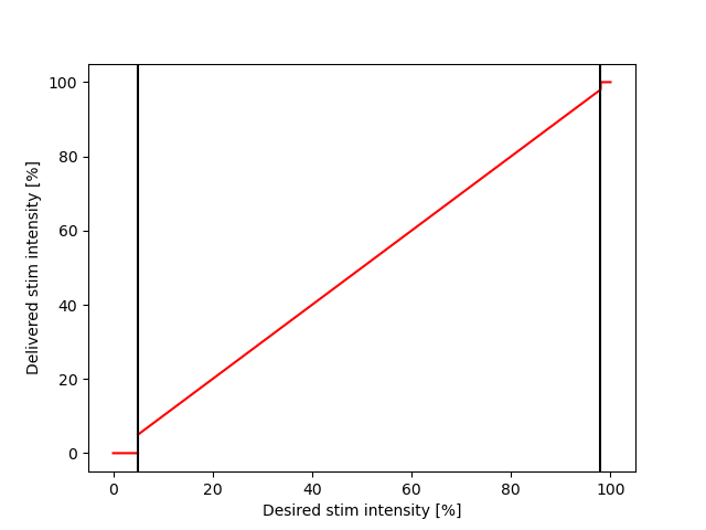
|
Available PWM frequencies |
50 - 40kHz. Possible to use slower frequencies by changing the source code. |
Depends on stimulus intensity: 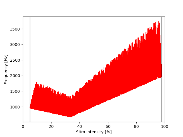
|
Theoretical precision |
0.02% at 200Hz |
variable but always better than 0.05% 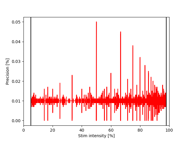
|
VR capability |
Can use rugged (i.e. checkerboard) and and smooth (i.e. gaussian) VR arenas without problems. |
Can generally present rugged (i.e. checkboard) VR arenas. There are limitations when using smooth (i.e. gaussian) VR arenas: Lower Intensities (i.e. 10%) seem to cause occasional flicker. |
Time dependent stimulus |
Can use sharp (i.e. 0/50%, 0/99%) and and smooth (i.e. sigmoid ramps) stimulus files without problems. |
Can use sharp (i.e. 0/50%, 0/99%) stimulus files without problems. Smooth (i.e. sigmoid ramps) stimulus files at high framerates seem to cause occasional flicker. |
Conclusion |
Use this if you don’t need more than \(2{\mu}W/mm^2\) |
Use this if you must use more than \(2{\mu}W/mm^2\) Please be mindful of the limitations desribed above. |
Note
If you find additional limitations not listed here, please help us describe them. Please open a ticket on the the PiVR repository and provide the stimulus file in addition to the PiVR settings.
1.2. Building the Standard version
Warning
You will be handling sensitive electronic equipment. As you might be electrically charged, always touch something metallic that is connected to the ground before unpacking anything from an electrostatical shielding bag. A radiator will do fine.
Note
You can of course change the order of how to build the different parts. I build them in this order as there are necessary delays such as installing the operation system on the Raspberry Pi.
Note
We used an Ultimaker 3 with a Ultimaker Print Core AA (0.8mm) to print the PLA and a Ultimaker Print Core BB (0.8) to print the PVA support material. STL files were converted using Ultimaker CURA software.
Download the OS image here
Write the image onto an SD card (minimal tested SD size 16 Gb, larger should always work.)
Windows: Download and install Win 32 DiskImager and write the image on your SD card. Note: If you have Google Drive running you might have to shut it down for Win 32 DiskImager to run.
Linux and MacOS: Download Etcher and write the image on your SD card. Note: I had to amend the image file with ‘.img’ in order to select it.
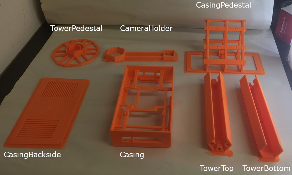
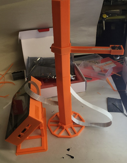
3D print each part in the folder PiVR/Hardware/3D printer files. We used an Ultimaker 3 and printed with Standard PLA. We used PVA as support material. For best results print Casing, CameraHolder, TowerBottom and TowerTop with support material.
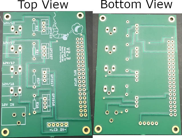
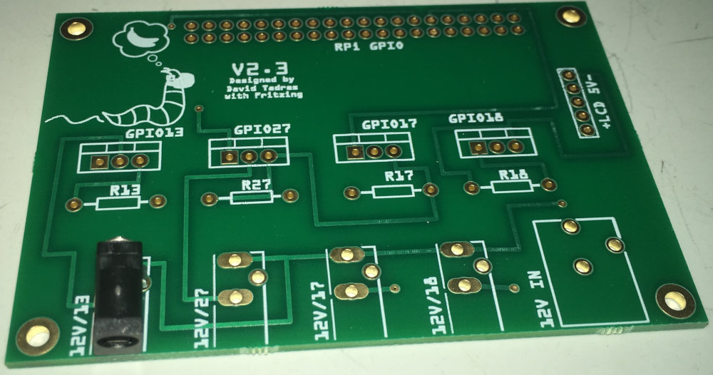
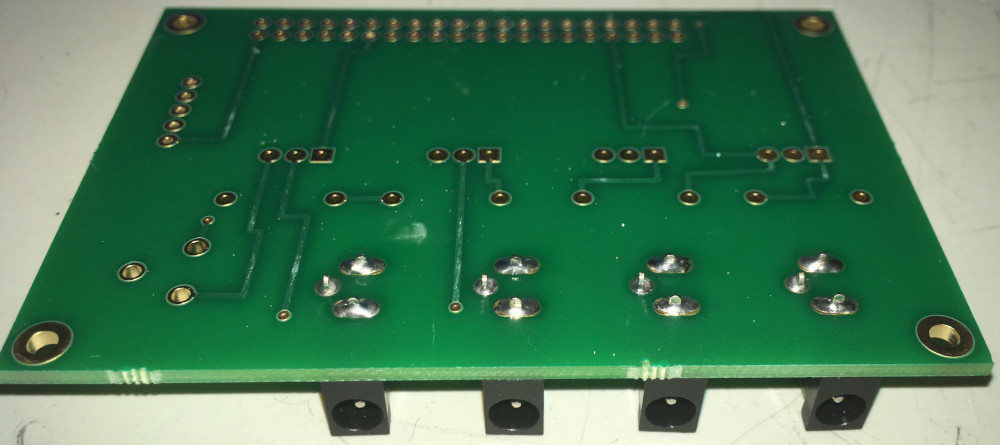
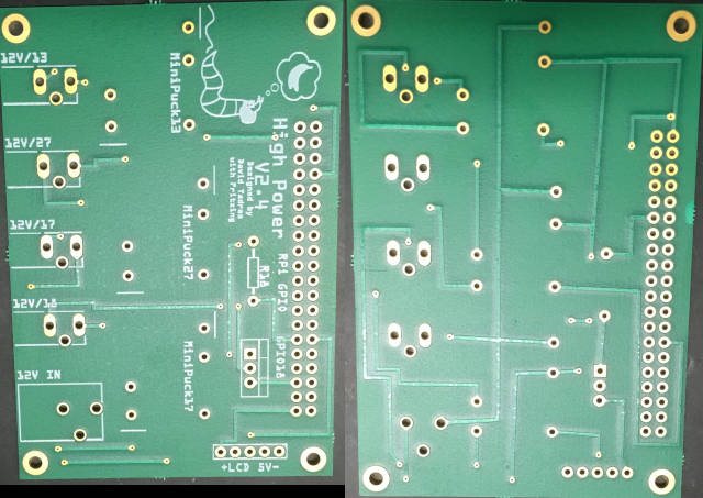
Obtain the Printed Circuit Board (PCB). Find the blueprint in PiVRHardwarePCB. I have used the software Fritzing to design the board. I have used the company Aisler.net to print the circuit boards.
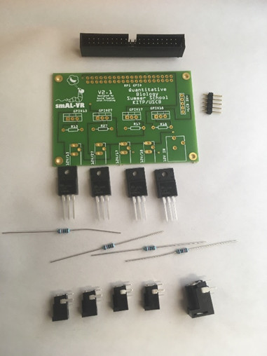
Get the following items to solder the PCB board:
Important
Before touching electrical components always touch something metallic that is connected to the ground. For example, a radiator.
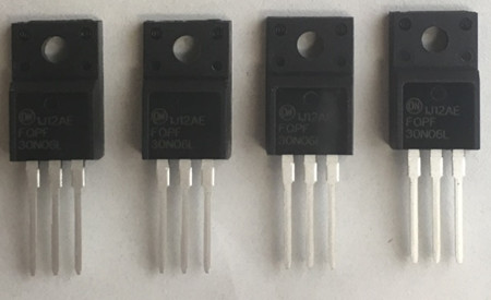
Four (4) Transistors: 30N06L
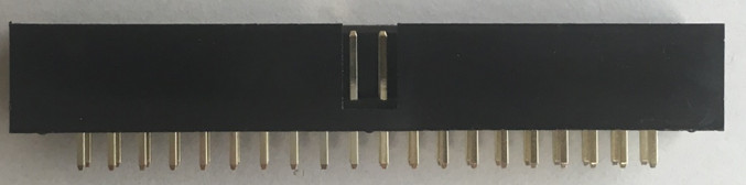
One (1) GPIO Header
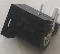
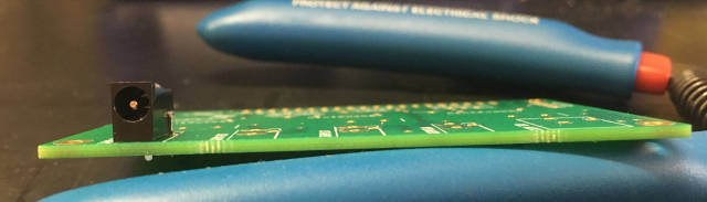
One (1) Barrel connector, 5.5mm Jack with 2.1mm center pole diameter
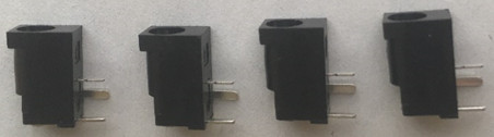
Four (4) Barrel connectors, 3.5mm Jack with 1.35mm center pole
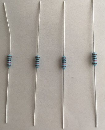
Four (4) \(10k{\Omega}\) resistors
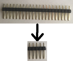
Break off a 5 pin stretch from the Breakaway Headers. This can be done using scissors or pliers.
Solder the components on the PCB. See this section for detailed soldering instructions.
Important
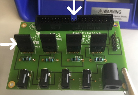
The correct orientation of the GPIO header and the Transistors is crucial for PiVR to work correctly.
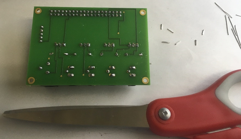
Cut off the excess wire of the resistors and the transistors, e.g. with scissors.
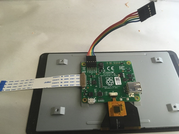
Unpack the Touchscreen, remove the stand-off screws. Attach the monitor cable that came with the Touchscreen and the 4” 5 pin cable.
Important
The monitor cable must be inserted in the correct orientation. When you look into the receptacle you’ll see that only one side has connectors. Make sure that you insert the cable’s connectors on the same side.
Important
Note the orientation of the 4” 5pin cable! Left is (+) while Right is (-).
Place the Casing on top of the Touchscreen (it will only fit in the shown orientation). Organize the 4” 5pin cable and the monitor cable as shown in the picture. Use the M2.5x10mm screws to fix the casing to the touchscreen.
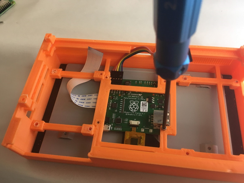
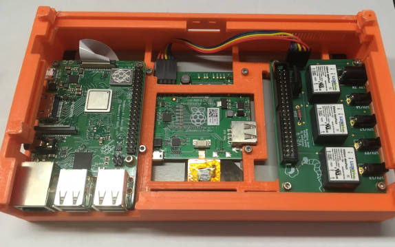
Connect monitor cable with the Raspberry Pi (with inserted SD card). Again, make sure you insert the cable in the correct orientation. Use M2.5x10 screws to attach the Raspberry Pi to the Casing.
Attach the PCB on the right side of the casing using M2.5x10mm screws. Plug the 4” 5pin cable into the PCB in the correct orientation as shown!
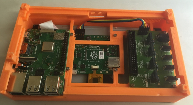
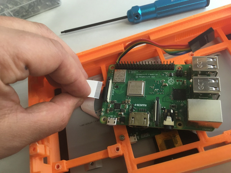
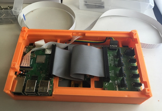
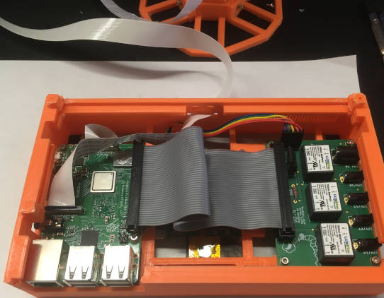
Use the GPIO Ribbon cable to connect the PCB with the Raspberry Pi. Thread the long camera cable through the slit as shown in the image below. Connect it to the Raspberry Pi camera port.
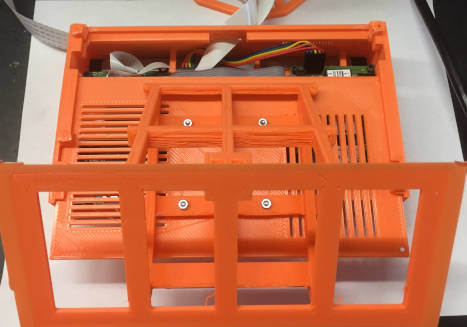
Attach the Backside to the CasingPedestal with M2.5x10 screws.
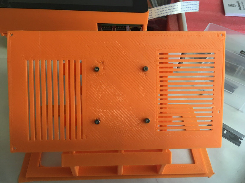
Slide the Backside into the Casing
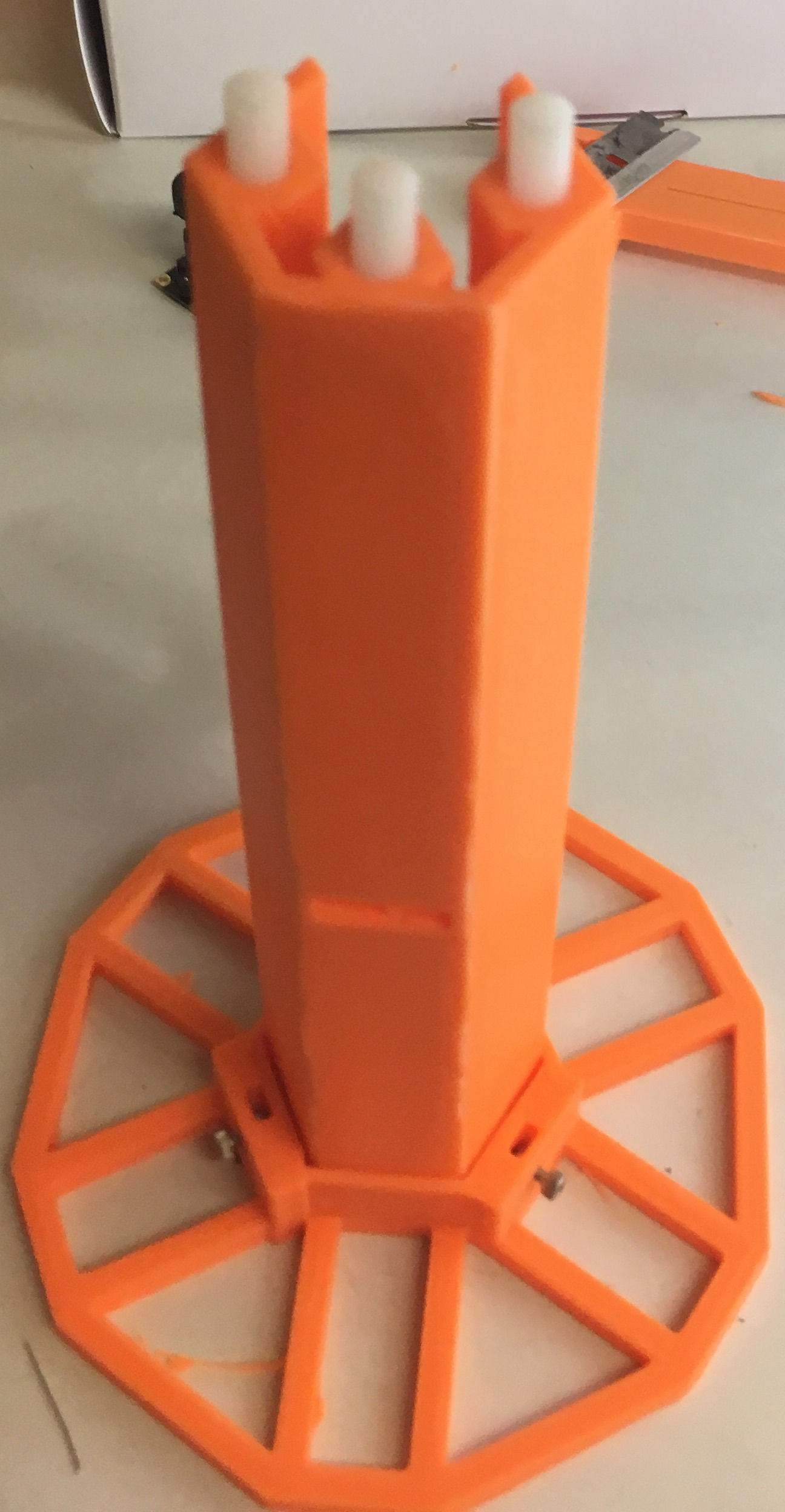
Drop a 2.5mm nut in each hole in the TowerPedestal. Use the M2.5x10 screws to attach the TowerBottom to the Tower Pedestal
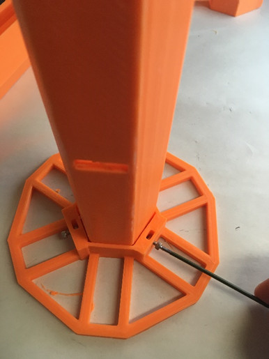
Using a hammer, drive the dowel pins into the TowerBottom. Then, attach the TowerTop to it. In principle you can stack more TowerTops on top.
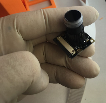
Attach the 800nm Longpass Filter to the Camera using Parafilm. It is best to wear gloves for this step.
Important
If you are not using the camera or lens in the image below, please provide your own undistort files before running experiments.
Thread the camera cable from the Casing through the slit in the TowerBottom and through the slit of the Camera Holder.
Important
Note the orientation to avoid having to curl the camera cable in the camera holder
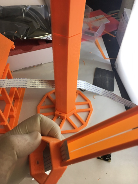
Attach the Camera Cable to the Camera in the correct orientation. Then, screw the camera to the Camera Holder using the M2.5x10 screws. It is not necessary to fixate the screws with nuts!
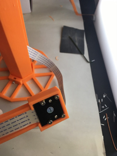
Drop a 2.5mm nut in the hole in the Camera holder and use it to fasten the M2.5x10 screw. Then attach the CameraHolder to the Tower.
On the first startup the screen will stay dark for a few minutes. Only start troubleshooting after > 5 (better 10) minutes. The following startups will be much faster. So now is a good time to build the arena:
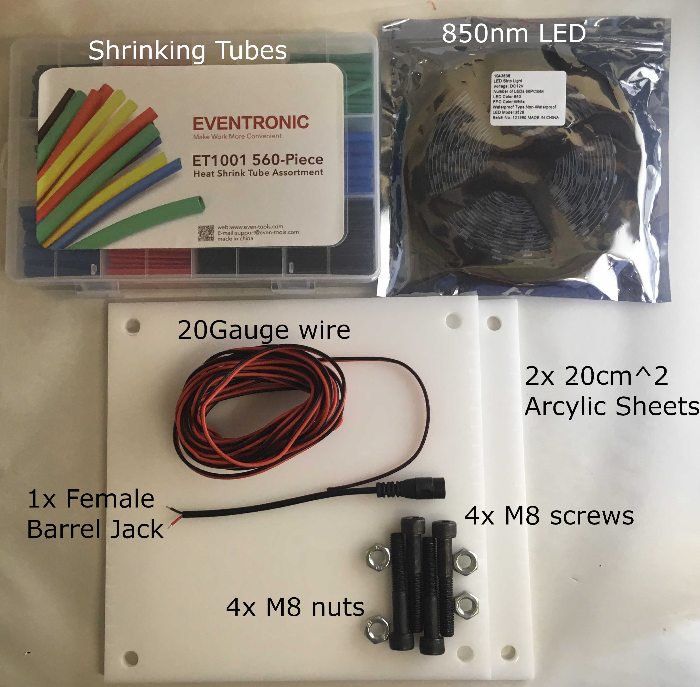
In the folder PiVR/Lasercutter_Files/ you can find two vector graphic files. This can be used to laser cut a 20-30cm arena, circular holes for M8 screws and small lines indicating the distance of 1cm on each side. For one arena you will need two acrylic plates.
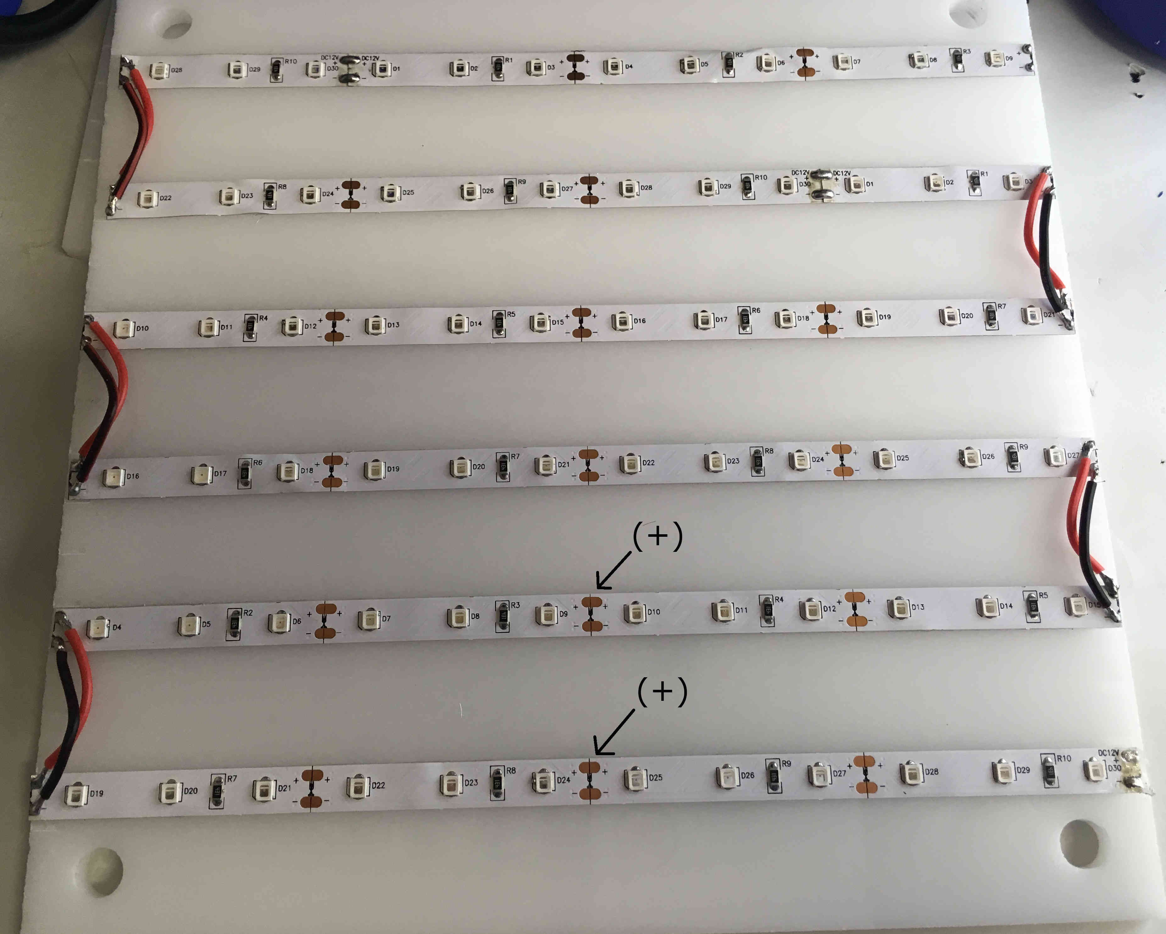
Cut the 850nm (infrared) LED strips to the desired length (e.g. 20cm on a 20cm Arena) and attach them to the arena. You can choose the horizontal distance yourself. I usually use a distance of 3cm.
Important
It will make soldering much easier if you make sure the (+) and the (-) between the LED strips are consistent!
Solder (+) to (+) from one side of the arena to the other. Then repeat for (-).
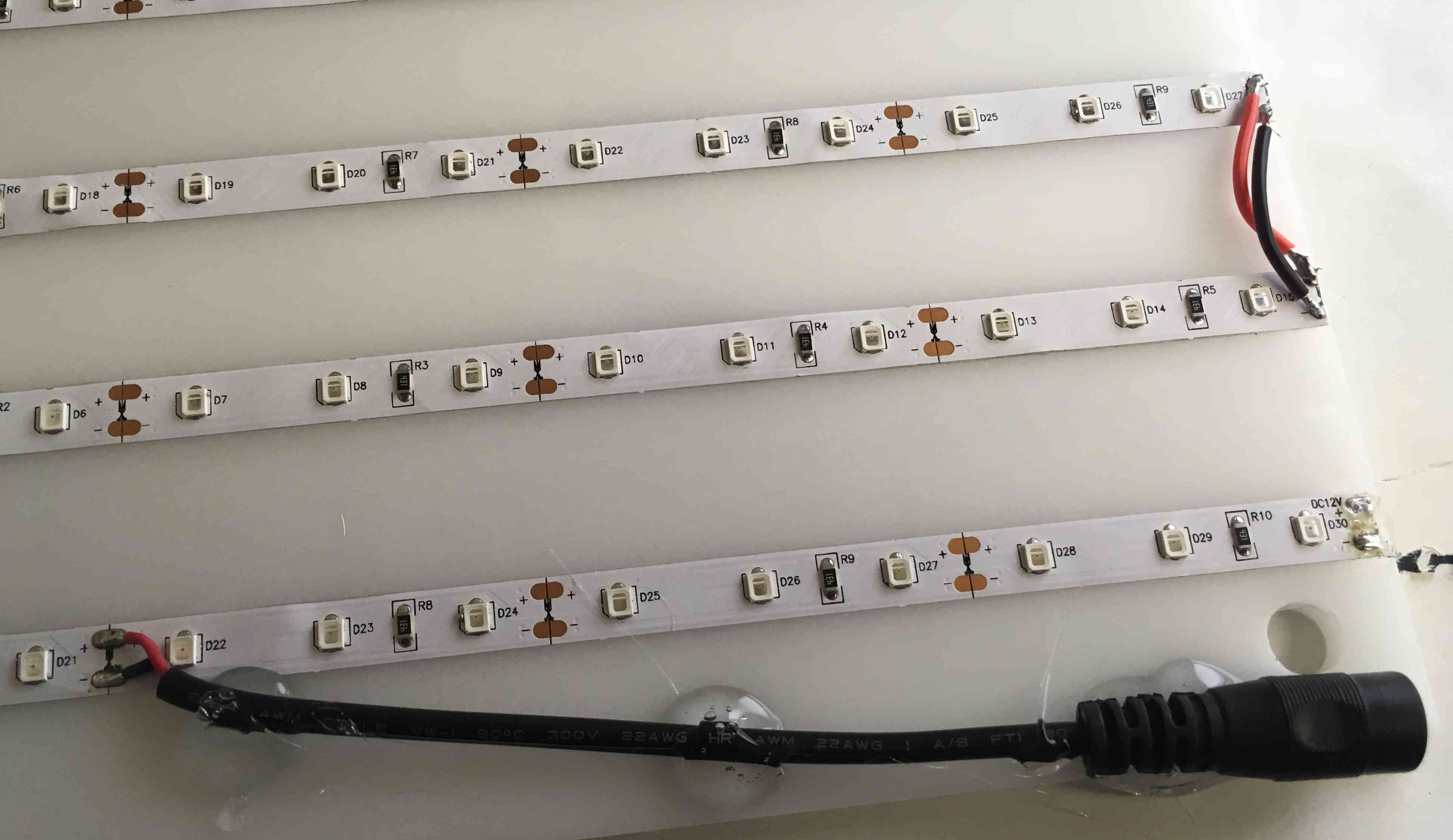
Attach the female Barrel Jack to a convenient copper dot on the LED strip. Then fix the Female Barrel Jack using super/hot glue gun. Make sure you are leaving space for the M8 screw to pass through.
Important
Usually the red wire of the Barrel Jack indicates (+)!
If you want to add a Stimulation LED strip (e.g. Red Stimulation light), just attach it in between the infrared LED strips, solder it as you did the 850nm LED strips. Then, attach the female Barrel connector at a convenient location and fix it using the hot glue gun.
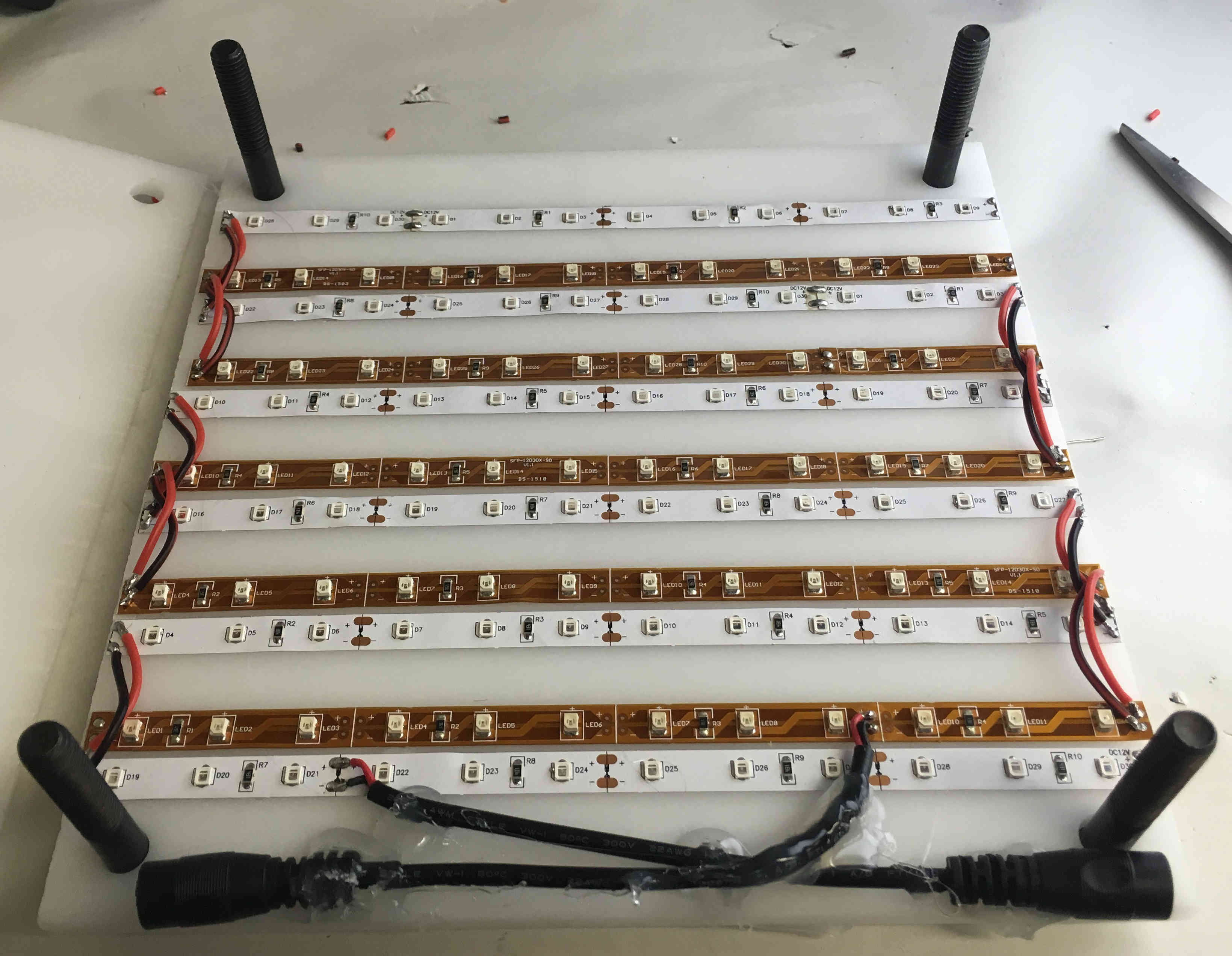
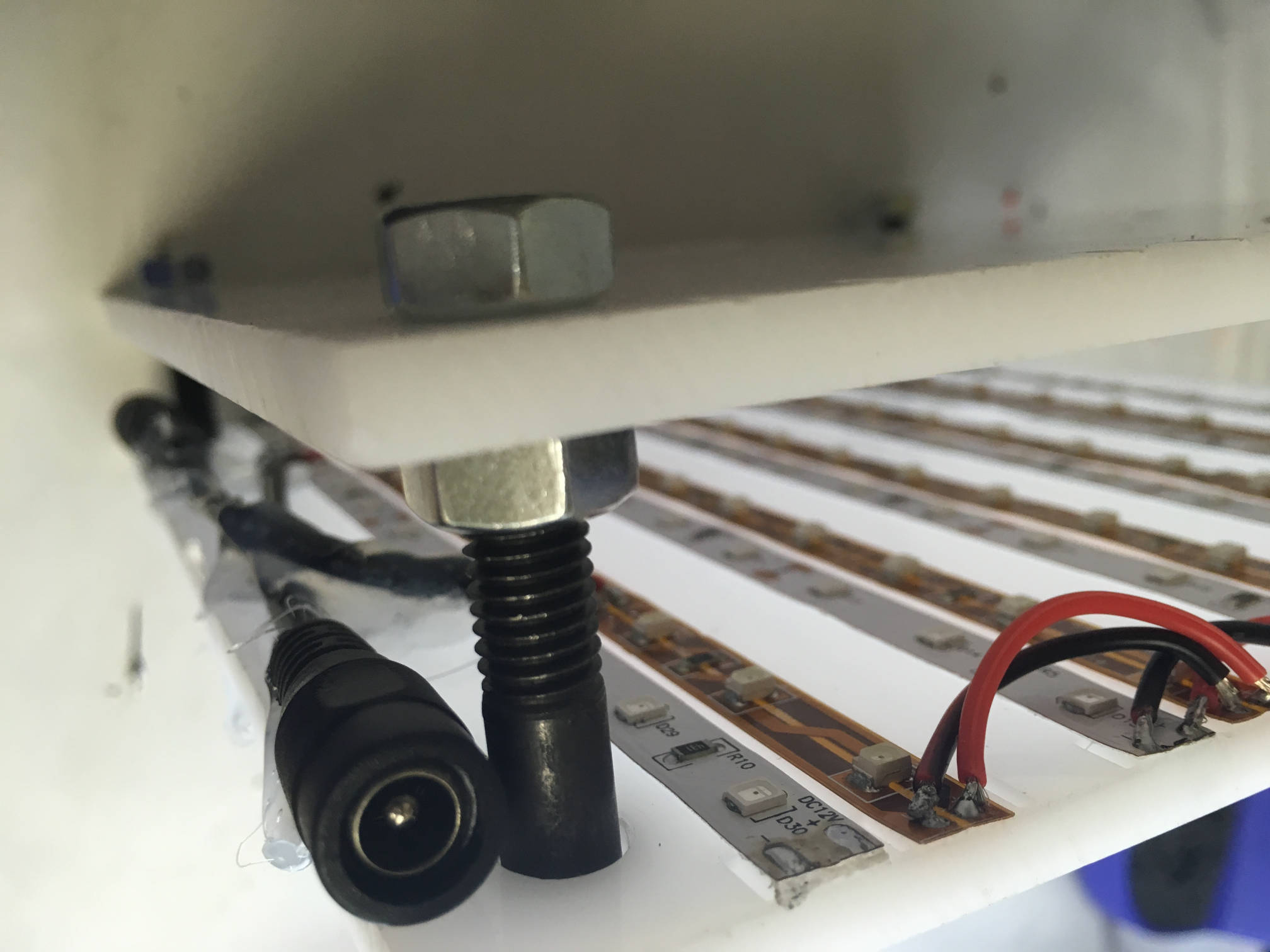
After inserting the M8 screws into the holes, thread a M8 nut on each of the screws about 2cm in. Put the second plate on top of the first and fasten it by threading a second M8 nut on top of the plate. Make sure the top plate is completely level by using a spirit level!
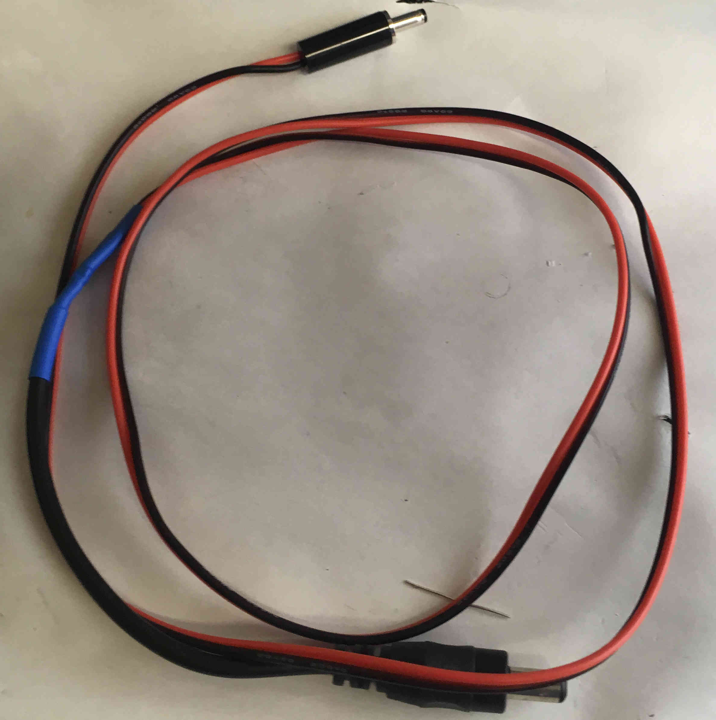
To connect PiVR with the arena, a cable needs to be constructed. You will need two 5.5mm Male Barrel Jack, two 3.5 male solderable Barrel Jacks and around 20 Gauge wire.
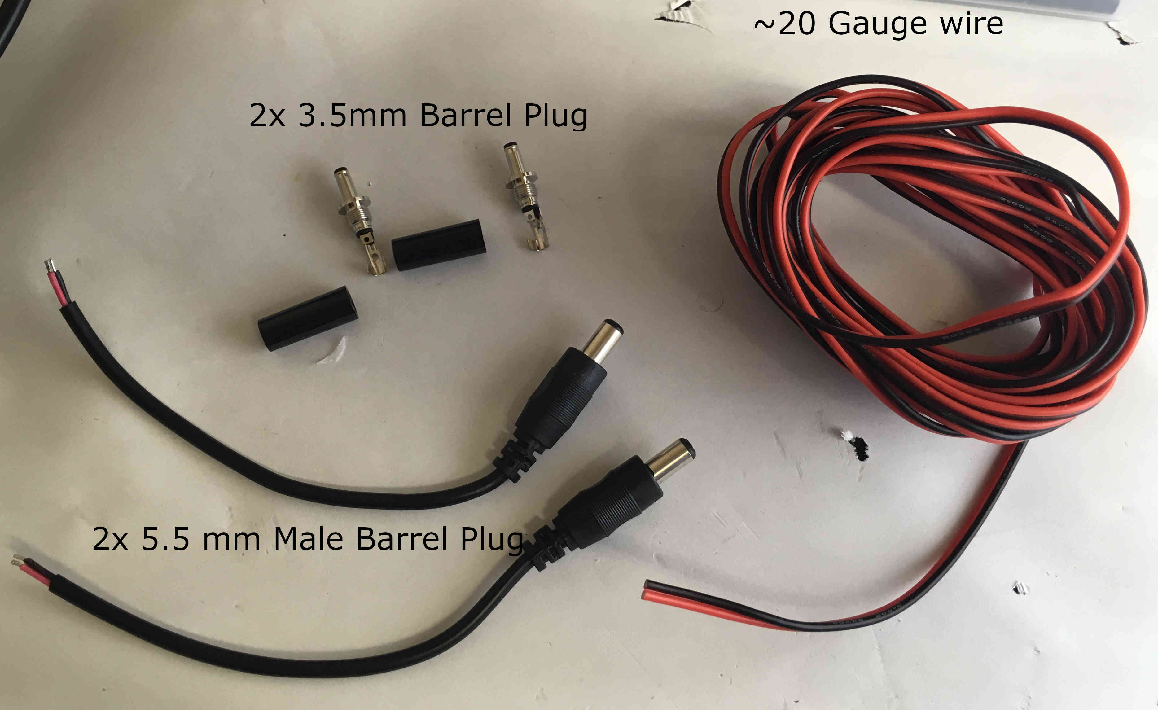
Click here to see how to construct a cable in detail. Briefly, start by cutting a reasonably long piece of the wire, e.g. 50cm, but this depends on your application. Attach one side of the cable to the 3.5mm barrel jack. You may solder it, but be careful to only use minute amounts of solder. Then solder on the 5.5mm barrel jack on the other side, fixing it using the shrinking tubes.
Start the PiVR software by double clicking on the shortcut on the Desktop. Under ‘Options’ Select ‘Optimize Image’.

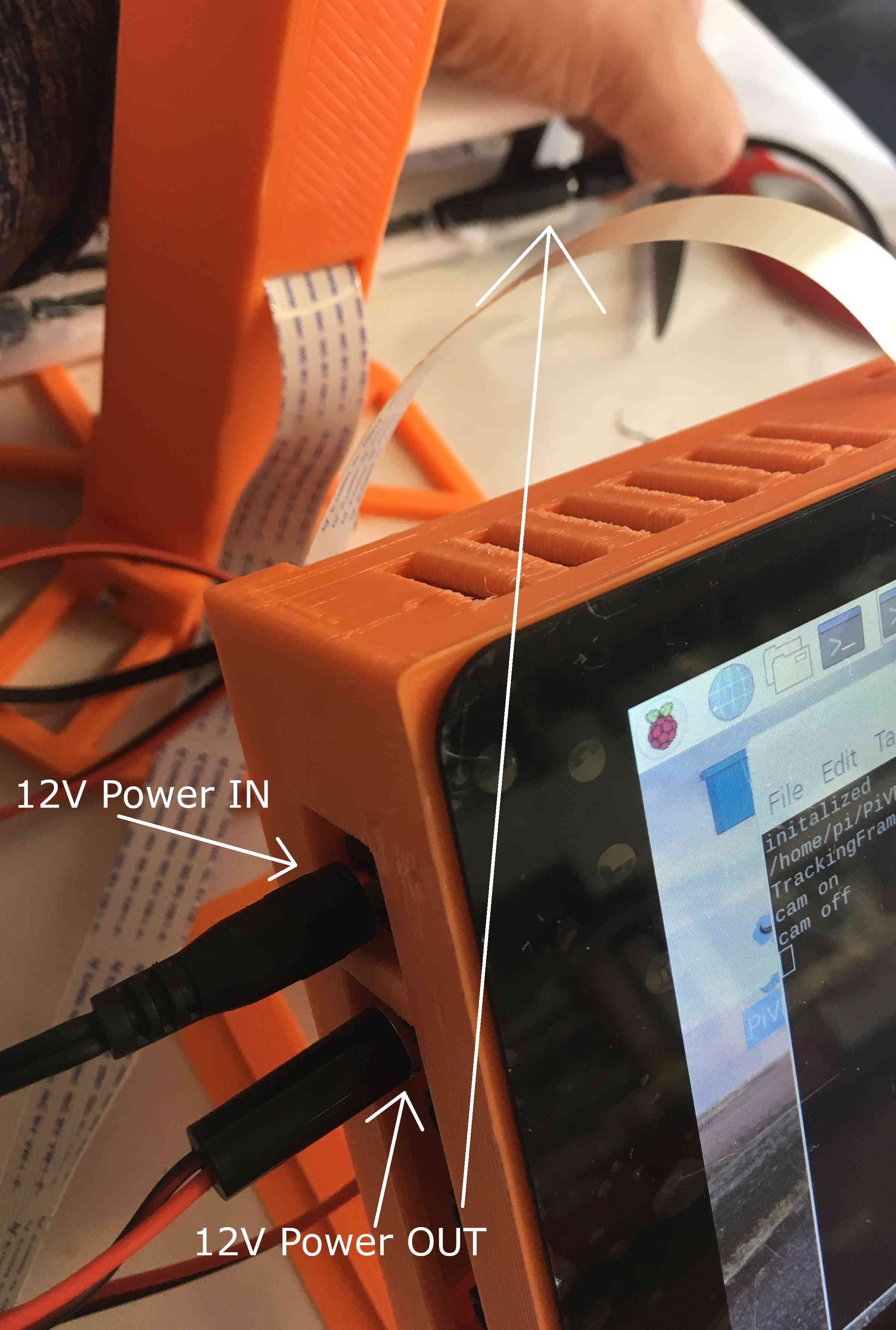
Connect the 12V power source (make sure you have an appropriate Ampere rating for the amount of LEDs you use!) to the 5.5mm Input on the setup. Do not plug it into the wall socket just yet!
Warning
Do not plug the 12V power source into the wall socket while you are handling the arena wires.
Then connect the 3.5mm cable with the appropriate receptacle closest to the 5.5mm plug. Then, plug the other side into the IR LEDs on the arena.
Now you can plug in the 12V power source into the wall socket.
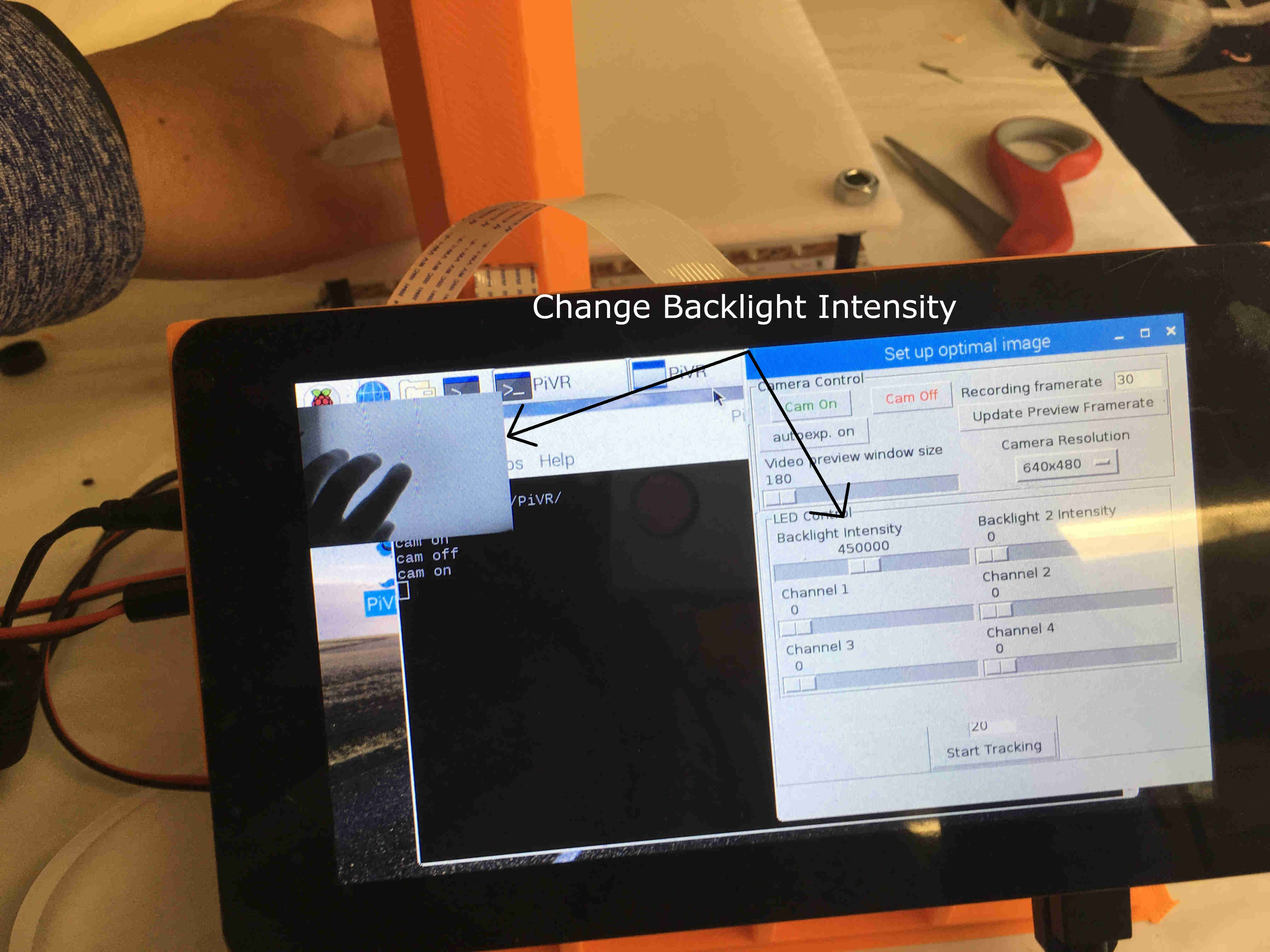
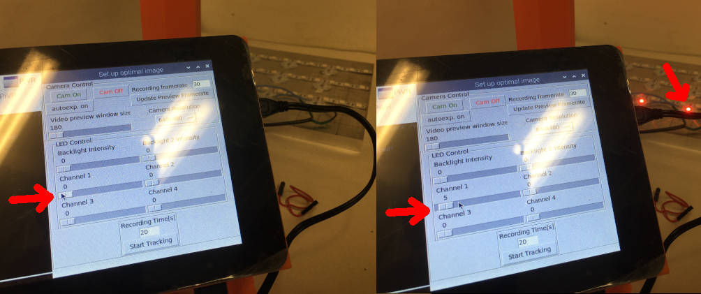
Turn the camera on (‘Cam On’). Then move the ‘Backlight Intensity’ slider to something like 400’000. You should see how the image on the top left of the screen lights up.
Note
Since the camera has a 800nm Longpass filter you shouldn’t see anything in the camera preview as long as the infrared light of the arena is off, unless you have a strong source of infrared radiation around, e.g. the Sun.
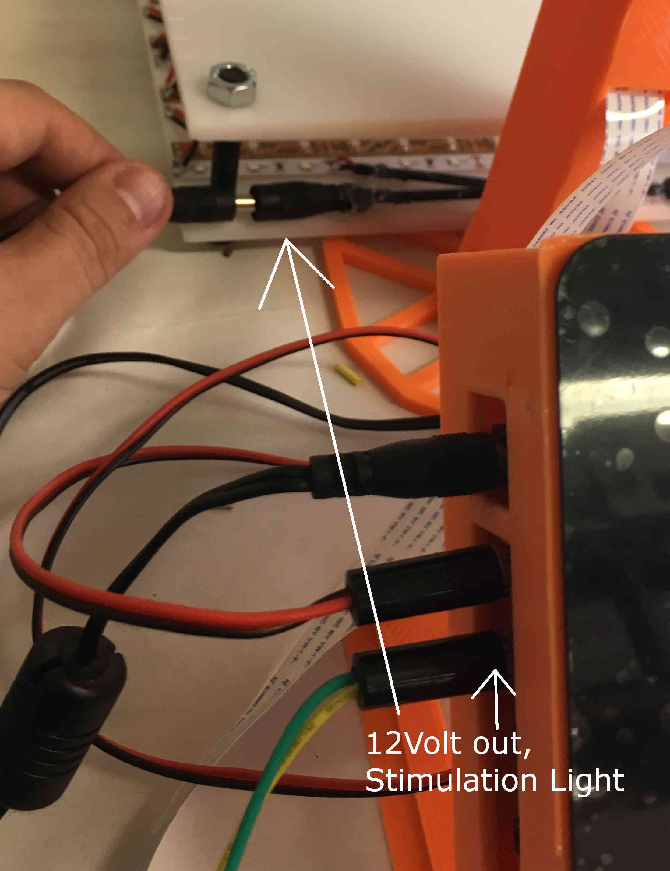
Connect a second 3.5mm cable just below the first. The other side goes into the first Stimulation Light in the arena.
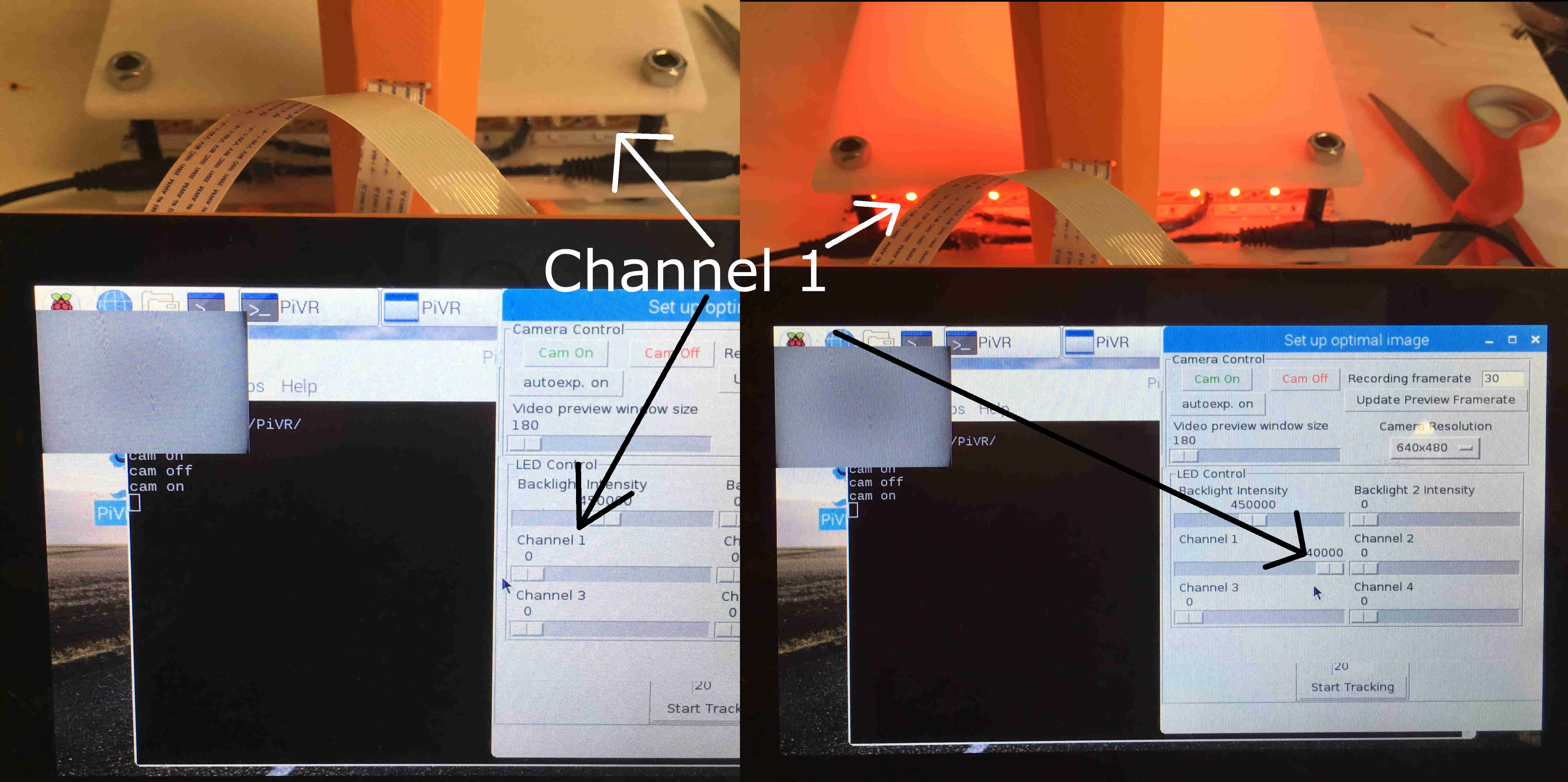
When moving the slider labelled ‘Channel 1’ the stimulation LED should light up.
If these tests have been successful, congratulations, you’ve built your own PiVR.
1.2.1. Detailed PCB soldering instructions (Standard Version)
Warning
Important! Make sure that the pins are not connected due to imprecise soldering!
I prefer to solder the components on the PCB board in this particular sequence as I find it easiest to keep the components in place. Otherwise there is no reason to not solder components in any sequence you prefer!
To solder the PCB board, you will need the following elements:
Four (4) Transistors: 30N06L
One (1) GPIO Header
One (1) Barrel connector, 5.5mm Jack with 2.1mm center pole diameter
Four (4) Barrel connectors, 3.5mm Jack with 1.35mm center pole
Four (4) \(10k{\Omega}\) resistors
Break off a 5 pin stretch from the Breakaway Headers. This can be done using scissors or pliers.
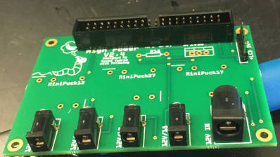
Take one of the small barrel plugs and place it into the leftmost possible spot on the PCB board as shown.
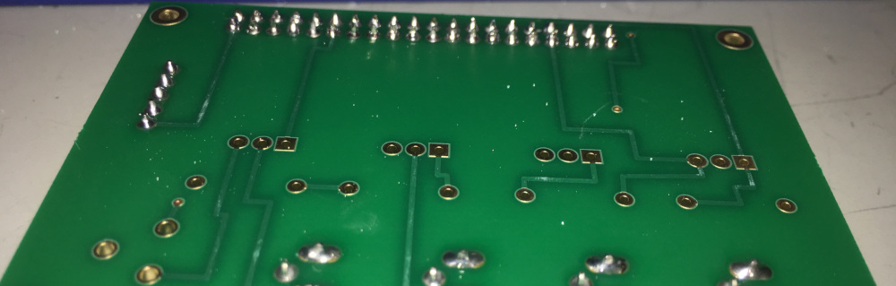
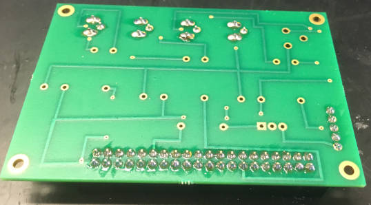
Flip the PCB board while holding the small barrel plug in place. By placing it on the table, it should not move and allow you to easily solder the three pins of the barrel plug to the PCB as shown.
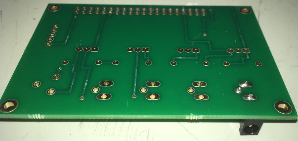
Continue to solder the other three small barrel plugs, one by one, onto the the PCB board.
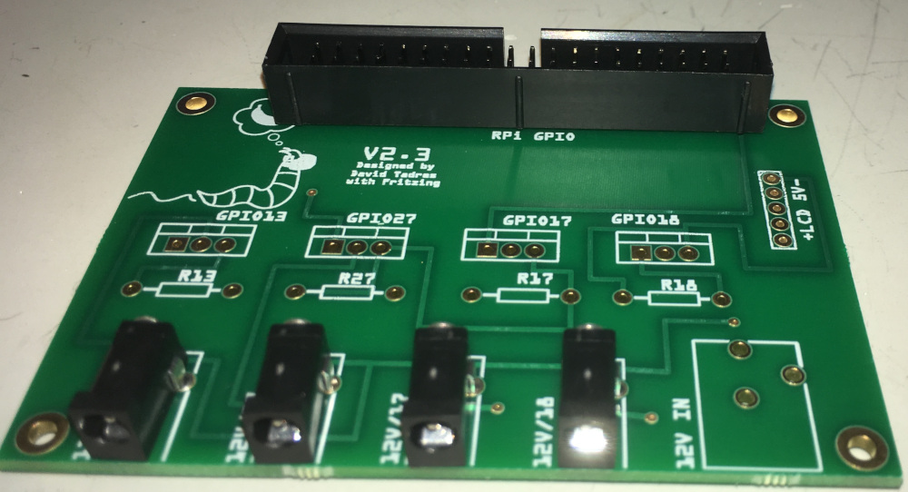
Next, place the GPIO header in exactly the orientation shown in the image below onto the PCB board.
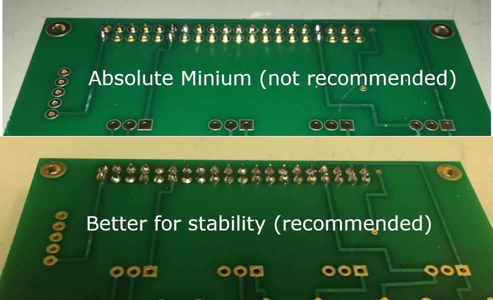
Flip the PCB board with the GPIO header around. As it now stands on the table it should be easy to solder. You do not have to solder every single pin to the PCB (minimum is shown on top picture) but it is recommended to solder more, ideally all. Be sure the solder between the pins does not touch
Place the 5-pin stretch of breakaway headers into the holes on the far right of the PCB. Make sure to place them in the correct orientation as shown in the picture (short side on the ‘back’ of the PCB).
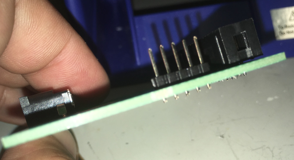
Flip the PCB with the 5-pin stretch of breakaway headers around and solder the header to the PCB board.
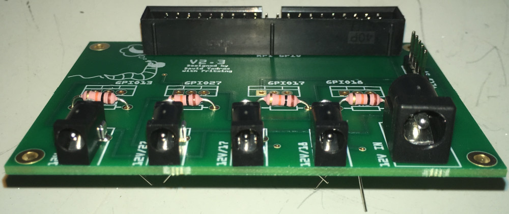
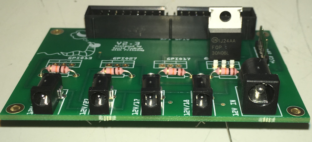
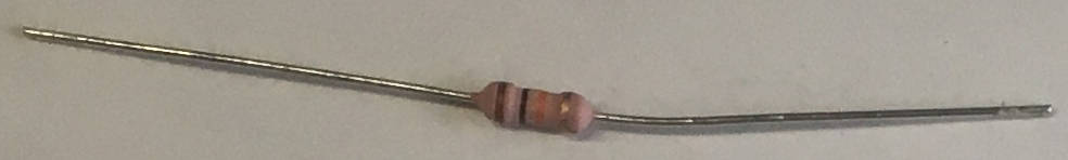
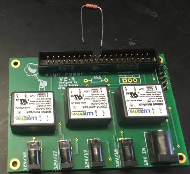
Now to the resistors. Place a resistor in the indicated position:
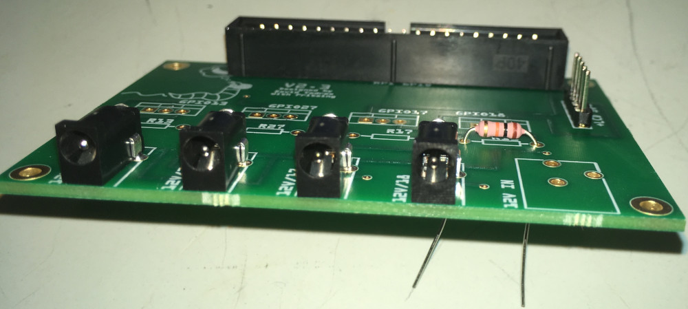
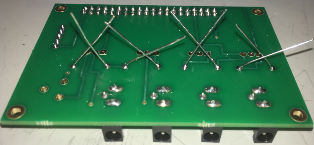
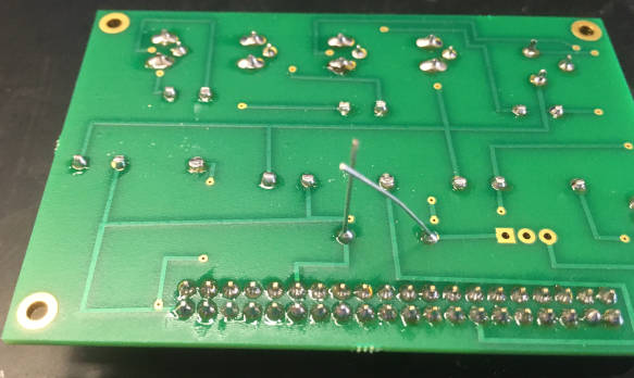
Flip the PCB board around. If the resistor falls out, just fixate it by bending the wire as indicated here. Then solder it the the PCB board.

Do the same for the other three resistors.
Now take the large barrel connector and place it on the PCB at the indicated position
Flip the PCB board around and solder the large barrel connector to the PCB board.
Next, take one of the transistors and place it exactly as shown onto the PCB board.
Flip the PCB board around and solder the transistor to the board. Make sure the solder of the different pins does not touch the contact of one of the other pins! Warning: Transistors are more heat sensitive compared to the other components you have used so far. Make sure to not let them heat up too much!
Do the same for the other three transistors.
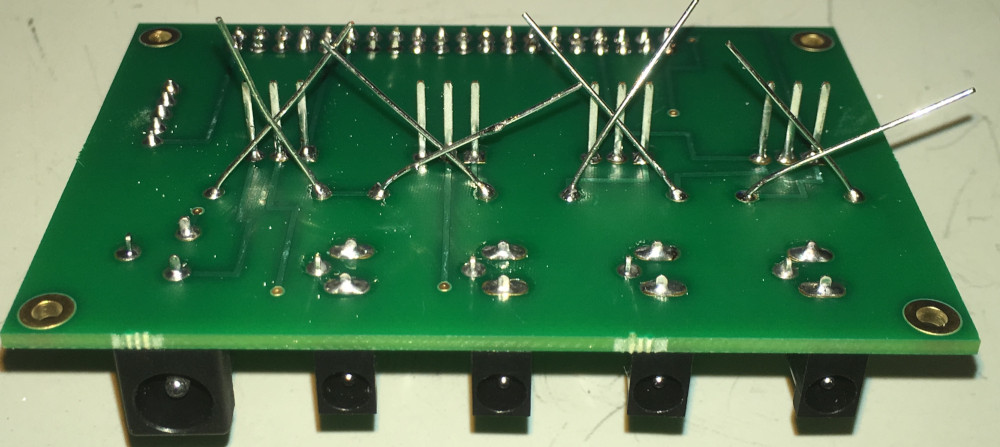
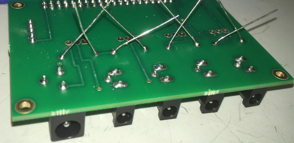
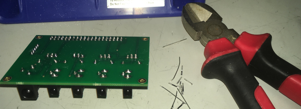
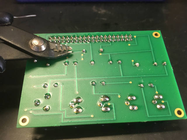
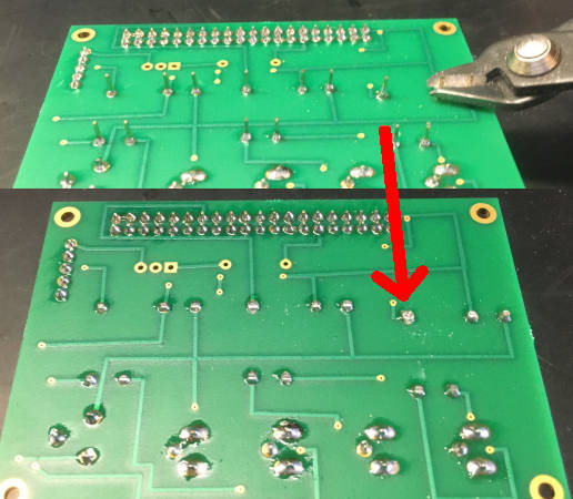
You must get rid of the elongated wiring of the transistors and especially the resistors as not doing so will 1) increase risk of shorting components and 2) it will physically be very hard to put the PCB board into the casing. While it is probably best to use the shown wire clipper, it is also possible to do that using normal scissor.
Congratulations - You have finished soldering your very own PCB board to build PiVR!
1.3. Building the High Powered Version
Warning
PLEASE avoid looking directly into the LED light. It might damage your eyes.
If you are in a situation where you might accidentally look into the LED light at 100% power, please consider purchasing eye saftey googles for the wavelength you are using, for example from here.
Warning
You will be handling sensitive electronic equipment. As you might be electrically charged, always touch something metallic that is connected to the ground before unpacking anything from an electrostatical shielding bag. A radiator will do fine.
Note
You can of course change the order of how to build the different parts. I build them in this order as there are necessary delays such as installing the operation system on the Raspberry Pi.
Note
We used an Ultimaker 3 with a Ultimaker Print Core AA (0.8mm) to print the PLA and a Ultimaker Print Core BB (0.8) to print the PVA support material. STL files were converted using Ultimaker CURA software.
Download the OS image here
Write the image onto an SD card (minimal tested SD size 16 Gb, larger should always work.)
Windows: Download and install Win 32 DiskImager and write the image on your SD card. Note: If you have Google Drive running you might have to shut it down for Win 32 DiskImager to run.
Linux and MacOS: Download Etcher and write the image on your SD card. Note: I had to amend the image file with ‘.img’ in order to select it.
3D print each part in the folder PiVR/Hardware/3D printer files. We used an Ultimaker 3 and printed with Standard PLA. We used PVA as support material. For best results print Casing, CameraHolder, TowerBottom and TowerTop with support material.
Obtain the Printed Circuit Board (PCB). Find the blueprint in PiVRHardwarePCB. I have used the company Aisler.net to print the circuit boards.
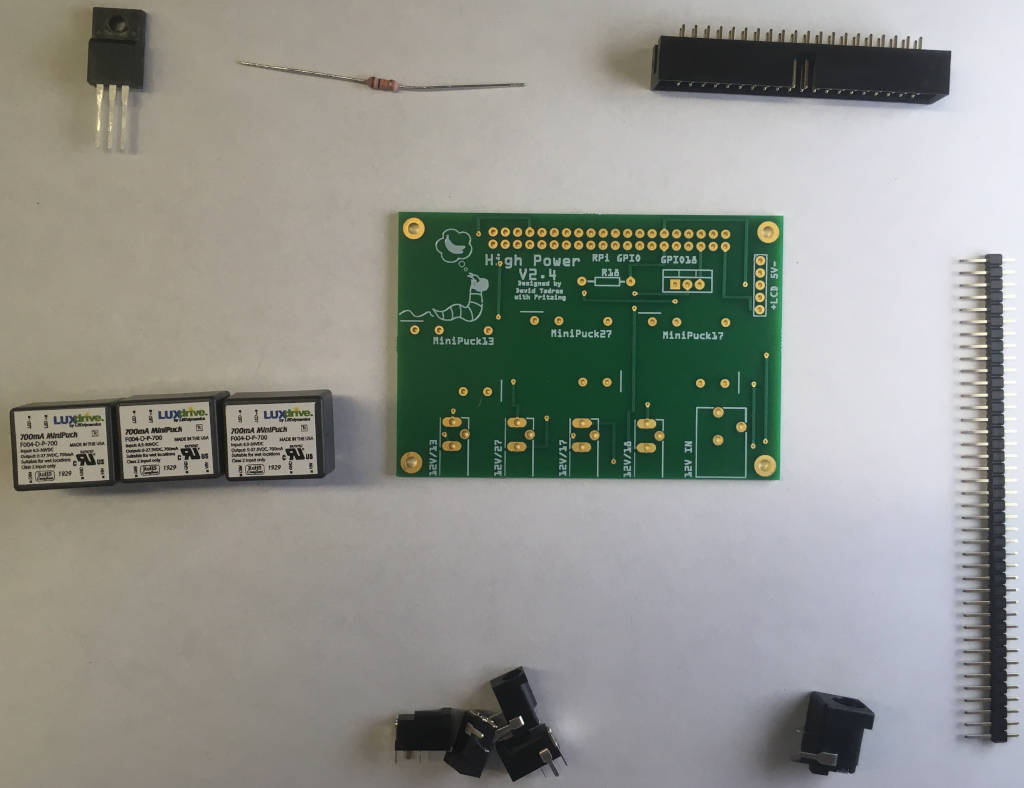
Get the following items to solder the PCB board:
Important
Before touching electrical components always touch something metallic that is connected to the ground. For example a radiator.
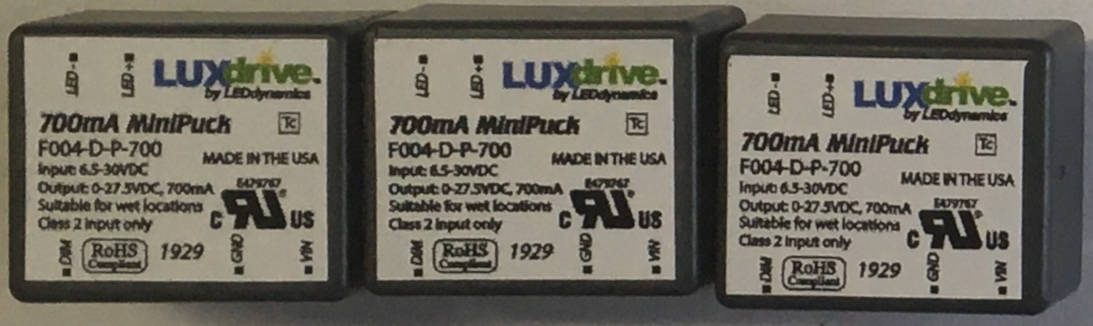
Three (3) LED driver “MiniPuck”, 700mA (or whatever strength you need)
One (1) Transistors: 30N06L
One (1) GPIO Header
One (1) Barrel connector, 5.5mm Jack with 2.1mm center pole diameter
Four (4) Barrel connectors, 3.5mm Jack with 1.35mm center pole
One (1) \(10k{\Omega}\) resistors
Break off a 5 pin stretch from the Breakaway Headers. This can be done using scissors or pliers.
Solder the components on the PCB. See this section for detailed soldering instructions.
Important
The correct orientation of the GPIO header and the Transistor is crucial for PiVR to work correctly.
Cut off the excess wire of the resistors and the Transistors, e.g. with scissors.
Unpack the Touchscreen, remove the stand-off screws. Attach the monitor cable that came with the Touchscreen and the 4” 5 pin cable.
Important
The monitor cable must be inserted in the correct orientation. When you look into the receptacle you’ll see that only one side has connectors. Make sure that you insert the cable’s connectors on the same side.
Important
Note the orientation of the 4” 5pin cable! Left is (+) while Right is (-).
Place the Casing on top of the Touchscreen (it will only fit in the shown orientation). Organize the 4” 5pin cable and the monitor cable as shown in the picture. Use the M2.5x10mm screws to fix the casing to the touchscreen.
Connect monitor cable with the Raspberry Pi (with inserted SD card). Again, make sure you insert the cable in the correct orientation. Use M2.5x10 screws to attach the Raspberry Pi to the Casing.
Attach the PCB board on the right side of the casing using M2.5x10mm screws. Plug the 4” 5pin cable into the PCB in the correct orientation as shown!
Use the GPIO Ribbon cable to connect the PCB board with the Raspberry Pi. Thread the long camera cable through the slit as shown in the image below. Connect it to the Raspberry Pi Camera port.
Attach the Backside to the CasingPedestal with M2.5x10 screws.
Now just slide the Backside (with attached CasingPedestal) into the Casing.
Drop a 2.5mm nut in each hole in the TowerPedestal. Use the M2.5x10 screws to attach the TowerBottom to the Tower Pedestal
Using a hammer, drive the dowel pins into the TowerBottom. Then attach the TowerTop to it. In principle you can stack more TowerTops on top.
Attach the 800nm Longpass Filter to the Camera using Parafilm. It is best to wear gloves for this step.
Important
If you are not using the camera or lens in the image below, please providee your own undistort files before running experiments.
Thread the camera cable from the Casing through the slit in the TowerBottom and through the slit of the Camera Holder.
Important
Note the orientation to avoid having to curl the camera cable in the camera holder
Attach the Camera Cable to the Camera in the correct orientation. Then screw the camera to the Camera Holder using the M2.5x10 screws. It is not necessary to fixate the screws with nuts!
Drop a 2.5mm nut in the hole in the Camera holder and use it to fasten the M2.5x10 screw. Then attach the CameraHolder to the Tower.
On the first startup the screen will stay dark for a few minutes. Only start troubleshooting after > 5 (better 10) minutes. The following startups will be much faster. So now is a good time to build the arena:
While the PiVR software is being installed on the Raspberry Pi (it will take > 10 minutes) the light pad can be built. Take the diffuser. If you have access to a lasercutter, you can use the svg file in ‘HardwareLasercutter_Files’ to prepare it. Alternatively, you can use a drill with a M8 or M8.5 drill bit to drill 4 holes as shown below.
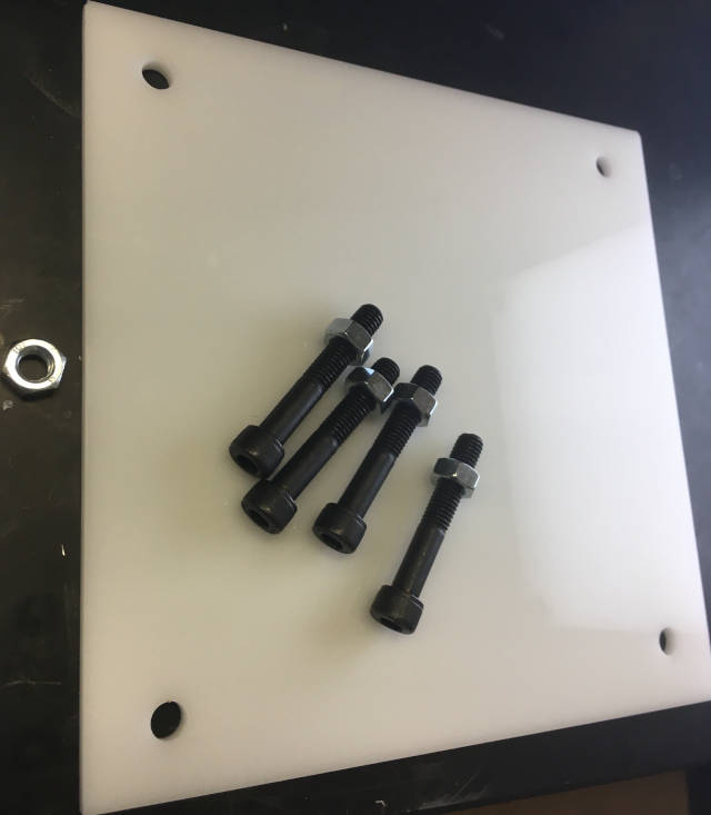
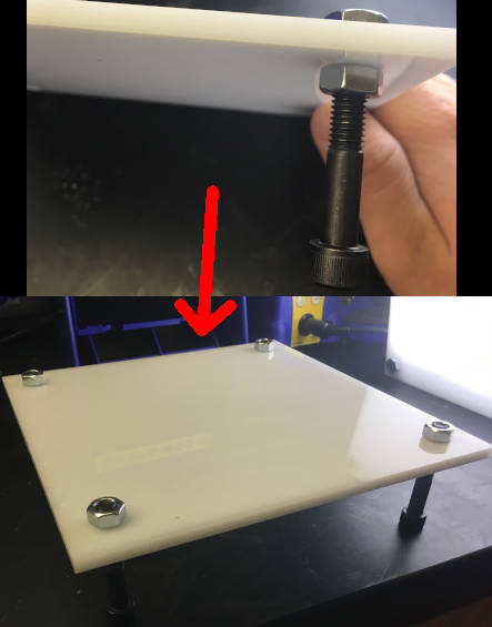
Put in the M8 screws with a nut below and above the diffuser as shown below.
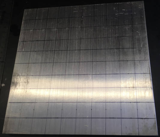
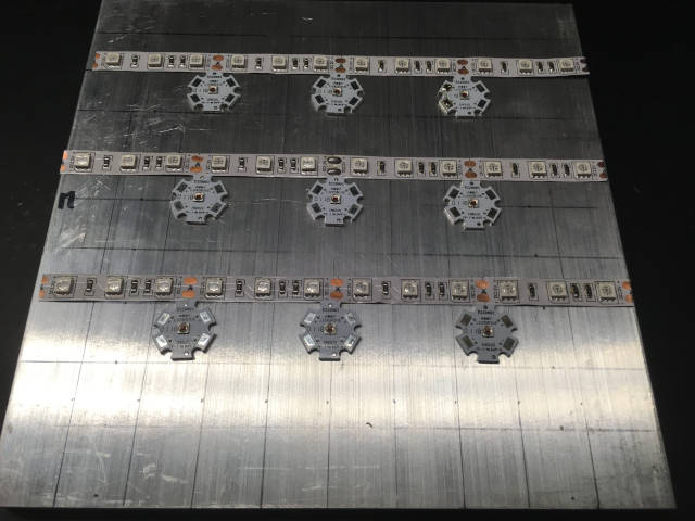
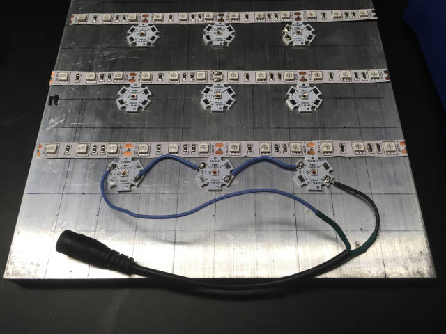
Next, take the Aluminum heat sink and use a Sharpie and a scale to draw a grid with 1cm squares on the heat sink.
Take the thermally conductive double sided tape. I usually first attach it to the LED before sticking them on the aluminum heat sink.
Note
While you can chose LEDs of any wavelength, there is only space (and power) for up to 9 LEDs. In the interest of homogeneous illumination only a single wavelength can be used per light pad.
Do make sure that the LEDs are space 5 cm apart using the previously drawn grid.
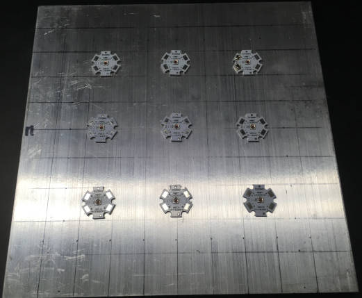
Now take the 850 nm LED strip for background illumination and place it in between the high powered LED lights.
Now, for the first row of LEDs, do the following: connect the (+) of the LED on the right with the (-) with the LED on its left.
Note
As heat transfers very quickly from the LED to the aluminum board it can be hard to liquify the solder on the LEDs. If you run into this problem, put some solder on the wire as well and keep it liquid until touching the contact on the LED. (Thank you Ruud Schilder for this suggestion)
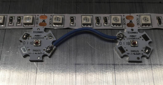
For the LED on the right, keep a longer, wire from (-). For the LED on the left, keep a longer wire from the (+).
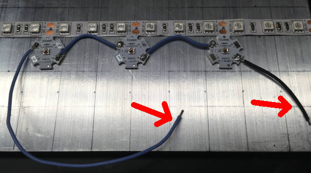
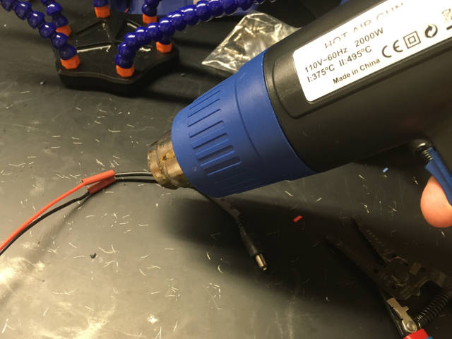
Take one of the smaller heat shrinking tubes and put it over the wire coming from the (+) of the LED. Take a female barrel plug and solder the red wire with the wire coming from the (+) of the LED row. When the solder has cooled down, push the heat shrink wire over the just soldered wire and heat it for stability of the cable.
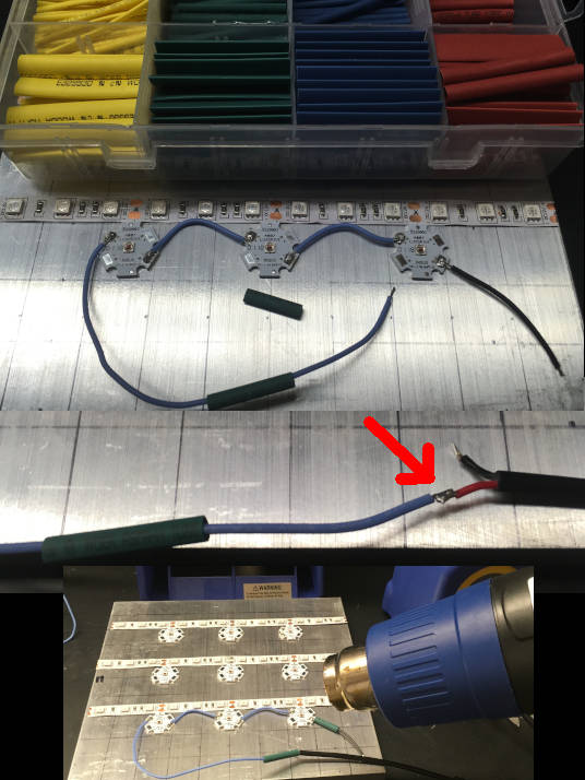
Repeat this for the wire coming from the (-) of the LED and connect it to the black wire of the barrel plug.
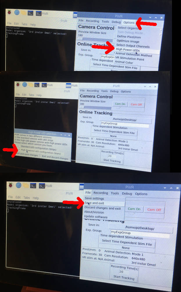
Now is a good time to test whether everything works as expected so far. First, head over to your PiVR setup. The installation should have finished by now. Before plugging in the power supply you need to change a setting in the PiVR software:
Go to “Options->High Power LEDs”.
In the popup window select “High Powered LED configuration” and hit “Exit and save changes”.
To restart the PiVR software, go to “File->Save and Exit”.
You also have to manually adapt the Pulse Width Modulation (PWM) frequency to the manufacturers recommendation. As you are using a MiniPuck, the manual states that the PWM frequency must be between 100-2kHz. See the software manual on how to modify the PWM frequency.
Next, you will have to prepare a cable as described here.
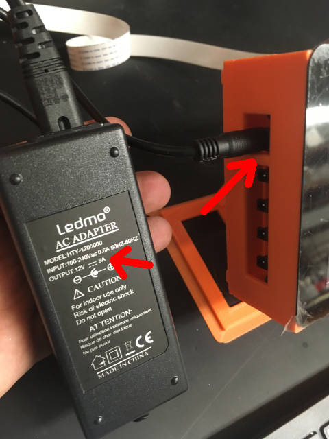
Connect an appropriate power supply (make sure it is 12V and has enough ampere for your particular setup) to the wall and to the PiVR setup.
In this particular example we are using 3 MiniPuck that have an output current of 700mA. The 850nm IR LEDs are rated at 24W/5M=2A of which we are using 3 x 20cm which is 2A x 0.06 = 120mA. The power supply needs to provide at least 3 x 700mA + 120mA = 2220mA. It is recommended to never be to close to the limit, hence I chose a 5A wall adapter.
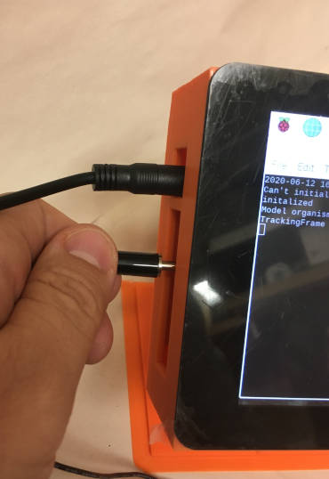
Connect the cable to the second small connector from the top. The large barrel connector needs to be connected to the female barrel plug you previously soldered to the LEDs.
Warning
Important: Only connect PiVR with the LED after changing the settings in “Options->High Power LEDs” to “High Powered LED configuration”. Otherwise the (very bright) LEDs will be completely turned on immediately.
To test the LED, go to “Options->Optimize Image” and use the slider below “Channel 1”. You should see the LED light up. If it does not, see here for some possible problems that might cause the failure.
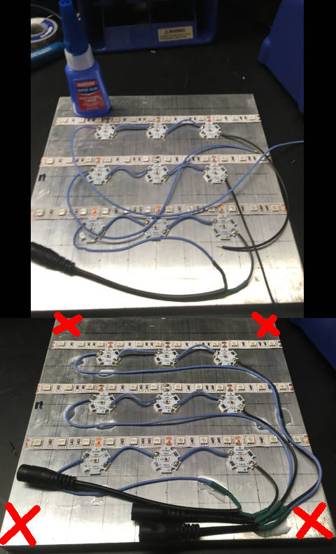
After confirming that the first row of LEDs works as expected, continue by soldering the other rows up exactly in the same fashion. You will quickly notice that there are too many cables around. I find that using super glue to organize the wires really does help. I recommend using gloves while handling super glue.
Do make sure to keep the edges of the aluminum heat plate free as indicated with the red crosses below.
It’s a good idea to test each row individually for functionality to quickly detect soldering errors.
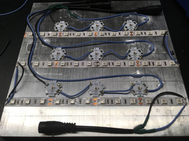
Finally, connect the 850nm infrared LED strips. From each row connect one of the (+) with the (+) on the next row and the repeat for the (-). Connect the red wire of the barrel plug with the (+) of the LED strip.
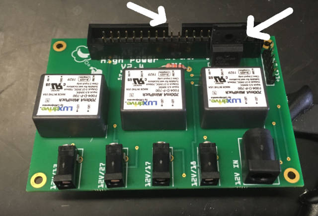
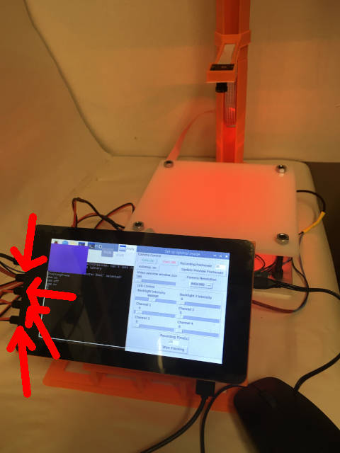
To test whether these LEDs work, take one of your cables and connect it to the top plug as shown below. Since these are infrared LEDs you will not be able to see with the bare eye, you need to use the PiVR camera. Then, go to “Options->Optimize Image” and drag the slider below ‘Background’ to the right. The LEDs should light up in the PiVR camera as shown in the image below.
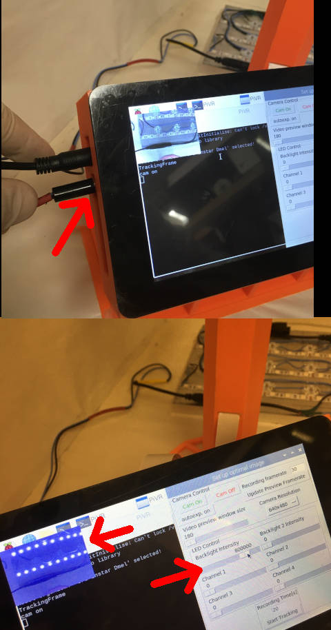
Now you are ready to test the complete setup: Make sure that the cable powering the infrared LEDs is connected to the top outlet at PiVR (top arrow).
The high-power LEDs can be connect in any order to the 3 remaining outlets (the three bottom arrows).
The diffuser should now be placed on top of the aluminum heat sink.
If these tests have been successful, congratulations, you’ve built your own high-power PiVR.
1.3.1. Detailed PCB soldering instructions (High Power Version)
Warning
Important! Make sure that the pins are not connected due to imprecise soldering!
I prefer to solder the components on the PCB board in this particular sequence as I find it easiest to keep the components in place. Otherwise there is no reason to not solder components in any sequence you prefer!
To solder the PCB board you will need the following elements:
One (1) Transistor: 30N06L

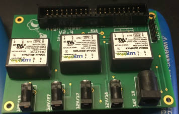
Three (3) LED Drivers “MiniPuck”
One (1) GPIO Header
One (1) Barrel connector, 5.5mm Jack with 2.1mm center pole diameter
Four (4) Barrel connectors, 3.5mm Jack with 1.35mm center pole
One (1) \(10k{\Omega}\) resistors
Break off a 5 pin stretch from the Breakaway Headers. This can be done using scissors or pliers.
Take one of the small barrel plug and place it into the leftmost possible spot on the PCB board as shown.
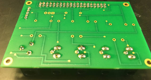
Flip the PCB board while holding the small barrel plug in place. By placing it on the table, it should not move and allow you to easily solder the three pins of the barrel plug to the PCB as shown.
Continue to solder the other three small barrel plugs, one by one, onto the the PCB board.
Next, place the GPIO header in exactly the orientation shown in the image below onto the PCB board.
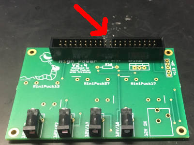
Flip the PCB board with the GPIO header around. As it now stands on the table it should be easy to solder. Be sure the solder between the pins does not touch
Place the 5-pin stretch of breakaway headers into the holes on the far right on the PCB. Make sure to place them in the correct orientation as shown in the picture (short side on the ‘back’ of the PCB).
Flip the PCB with the 5-pin stretch of breakaway headers around and solder the header to the PCB board.
Now take the large barrel connector and place it on the PCB at the indicated position
Flip the PCB board around and solder the large barrel connector to the PCB board.
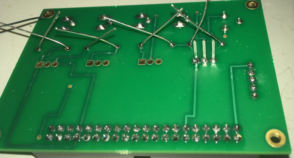
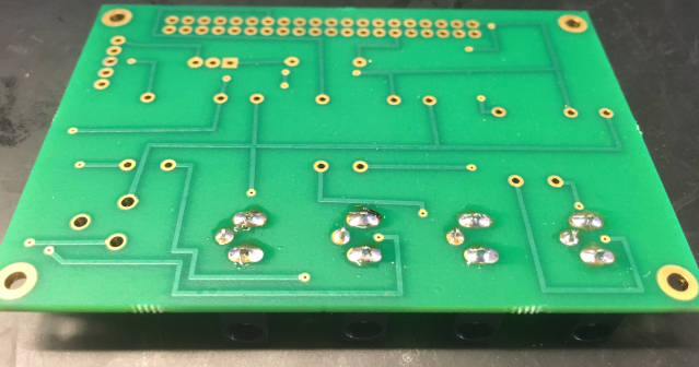
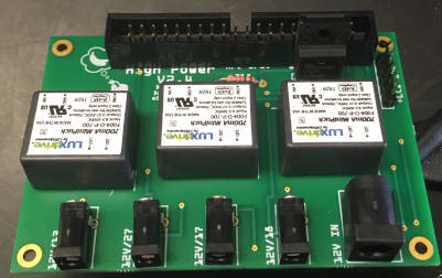
Take the MiniPuck LED drivers and put them into the labelled position on the PCB.
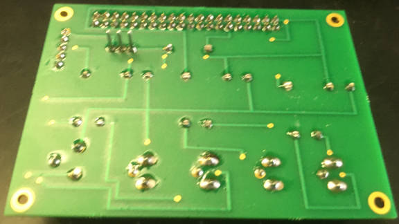
Turn the PCB around and solder each MiniPuck LED drivers to the PCB.
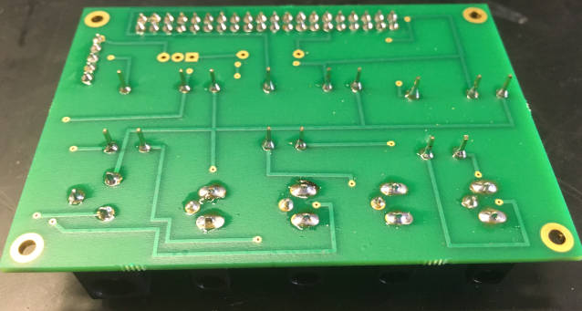
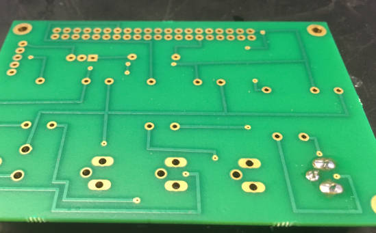
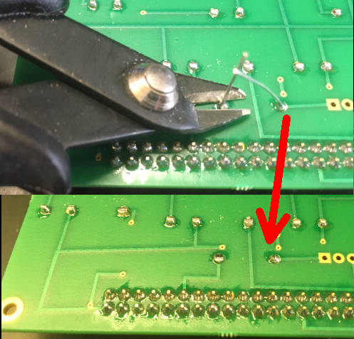
After soldering the MiniPuck LED drivers, flip the PCB again. You will notice that they have relatively long pins (top part of image). You need to remove them using a wire cutter.
Next, the \(10k{\Omega}\) resistor will be soldered to the PCB.
Flip the PCB board around. If the resistor falls out, just fixate it by bending the wire as indicated here. Then solder it the the PCB board.
Similar to the MiniPuck LED drivers above, you need to remove the leftover wire from the resistor after soldering it to the PCB.
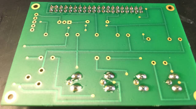
Next, take transistor and place it exactly as shown onto the PCB board.
Flip the PCB board around and solder the transistor to the board. Make sure the solder of the different pins does not touch the contact of one of the other pins! Warning: Transistors are more heat sensitive compared to the other components you have used so far. Make sure to not let them heat up too much!
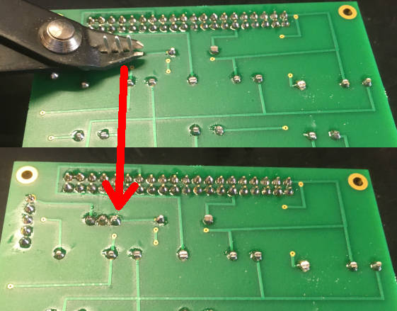
You must get rid of the elongated wiring of the transistors as not doing so will make it physically be very hard to put the PCB board into the casing. While it is probably best to use the shown wire clipper, it is also possible to do that using normal scissor.
Congratulations - You have finished soldering your very own PCB board to build the high-powered version of PiVR!
1.3.2. Testing homogeneity of the stimulation light
The principle of creating virtual realities depends on the homogeneity of the stimulation light. Below I will lay out how to measure the light intensity and strategies on how to handle inhomogeneity.
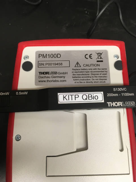
You can use any light/power meter. We have used the PM100D with the S130VC sensor (both from Thorlabs).
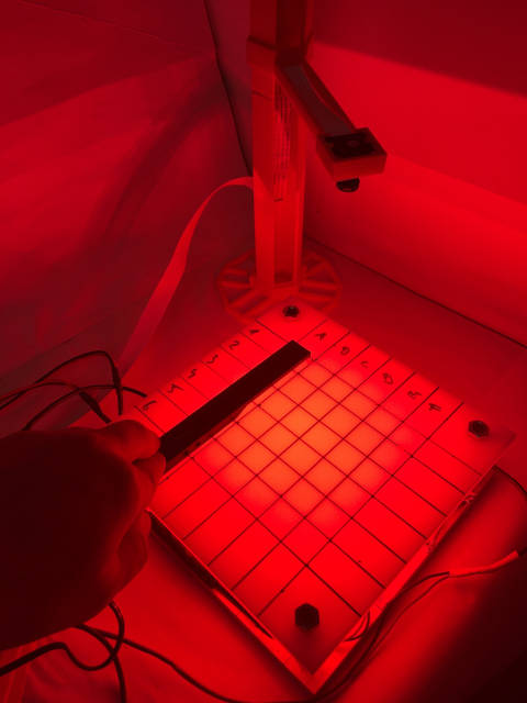
Draw a grid on the diffuser. I like to use numbers for rows and the alphabet for columns for clear separation while writing down the light intensity.
Wear eye protection and set the LED to 100%.
Warning
If you are using a unusual wavelength, e.g. deep blue at ~400nm or below you must also protect your skin! Please consult the LED manufacturer safety recommendation sheet.
Note
Why not using a low light intensity, e.g. 5%? PiVR is using Pulse Width Modulation (PWM) to control light intensity. The light meter is integrating the number of photons it reads over some time t (which can be hard to find in the light meter manual). PWM turns the LED on and off rapidly (as defined here). The easiest workaround is to just measure at 100% light intensity. Since PWM is guaranteed to scale linearly this will lead to accurate predictions of light intensities at e.g. 10% power.
Measure the light intensity for each square in the grid and note the light intensity. This will give you a good idea of the light intensity provided by the light pad and the homogeneity.
As you can quickly see, the light intensity is not perfectly homogeneous.
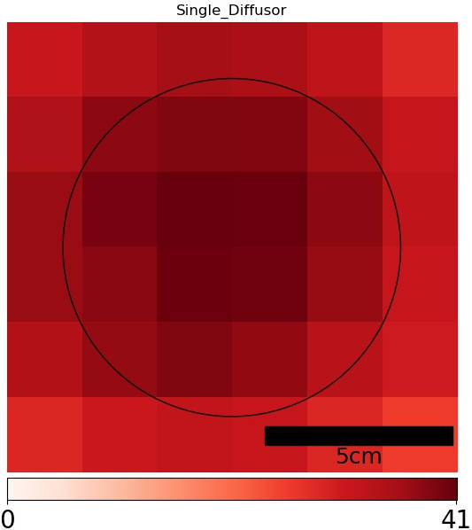
There are several ways to optimize for homogeneity: The easiest option is to add another diffuser plate. This will usually improve homogeneity but knock off quite a bit of the light intensity. If you compare the light intensity you can see that peak light intensity decreased from \(40{\mu}W/mm^2\) to \(10{\mu}W/mm^2\)
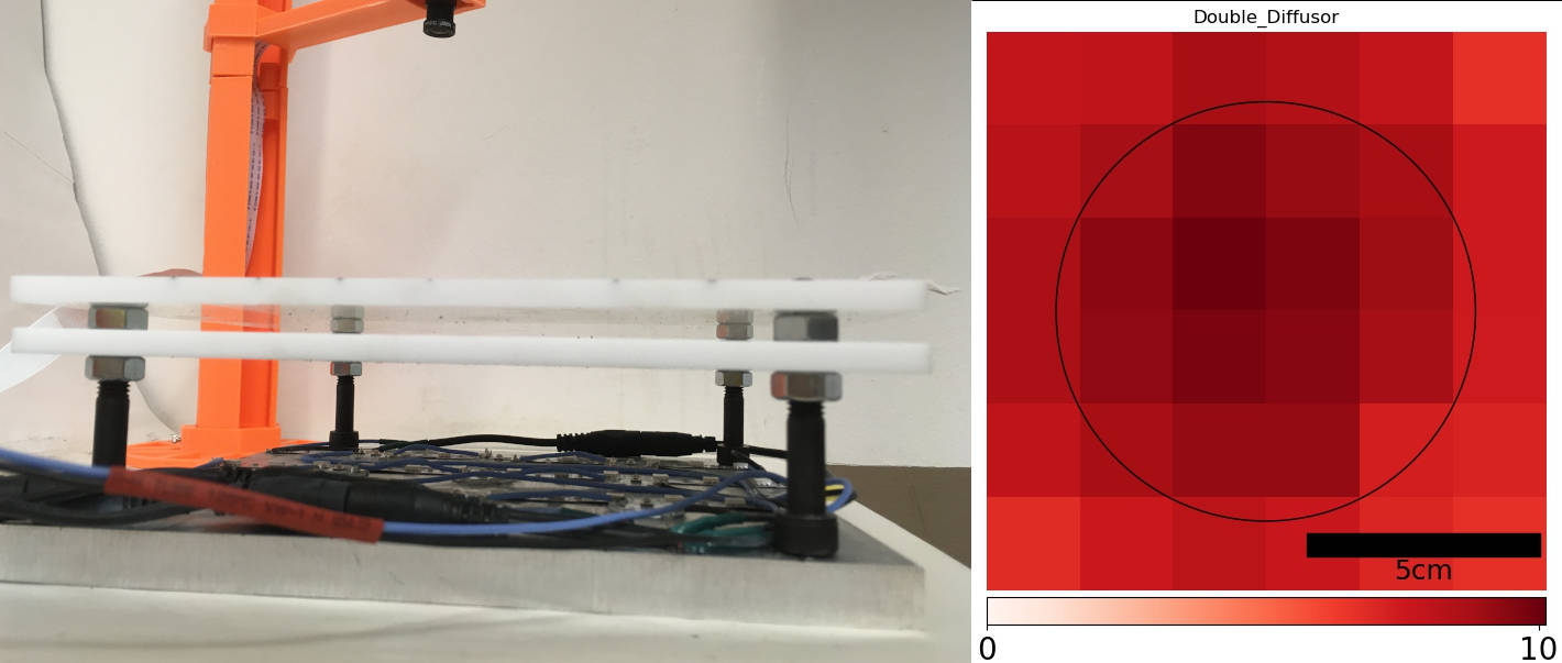
Finally, the reason why the light intensity falls of at the edges is due to the fact that quite a bit of light can escape by the sides instead of going through the diffuser. To counter this, the a reflective border can be used - just cardboard and aluminum foil.
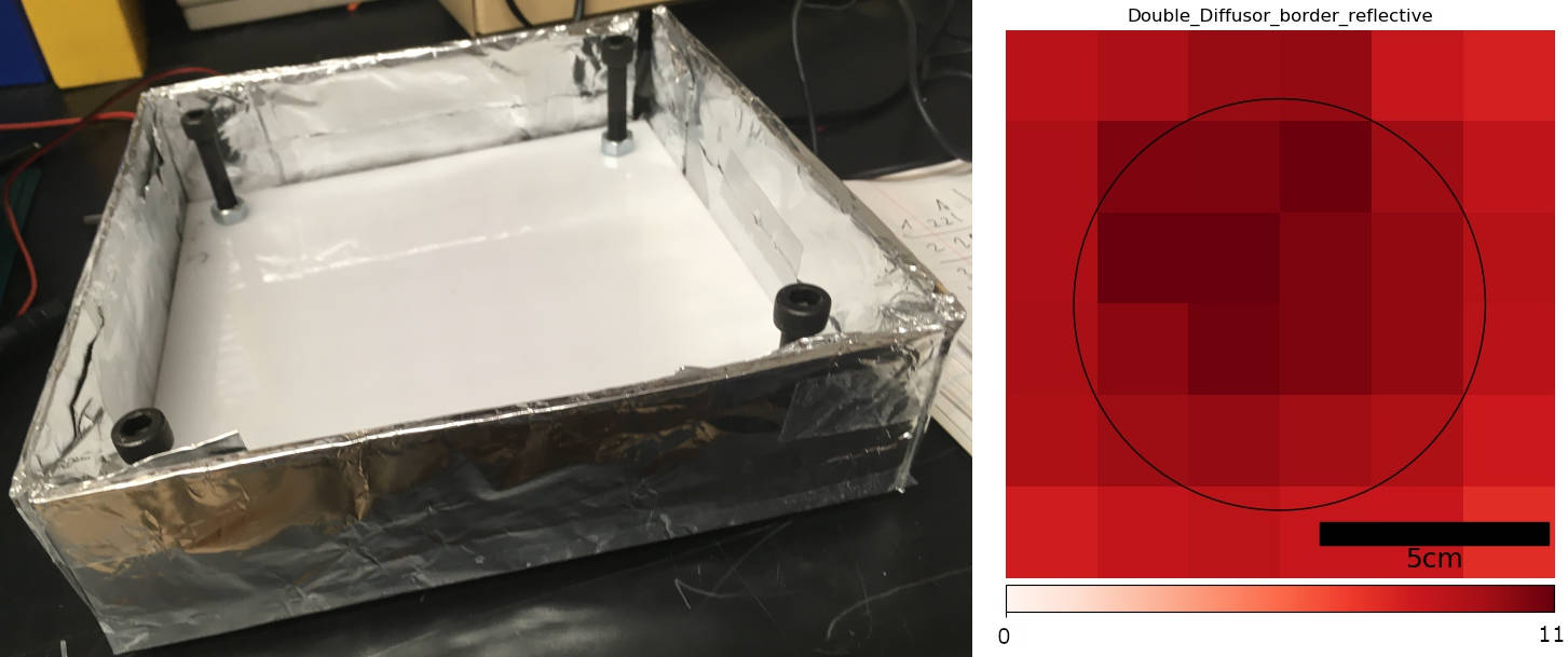
Conclusion: While the homogeneity in the center (indicated with a circle of diameter 90mm) is reasonable, it falls off at the edges. By trying different heights of the second diffuser plate and by introducing a border you can try to mitigate this.
There is an obvious software solution to this problem: For each plate, do these measurements save on the PiVR setup. When creating the virtual arena, tie stimulus intensity could take these measurments into account and normalize to the maximum intensity. This might be implemented in the future. Please check the gitlab repository for any open issues if you need this functionality.
1.4. Additional Information
1.4.1. Detailed soldering instructions (cable)
To construct 4 cables that connects PiVR with the light pad you will need the following components:
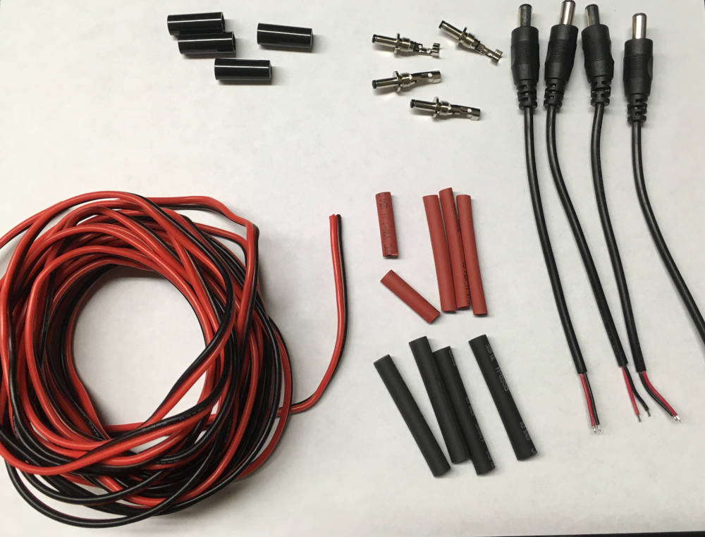
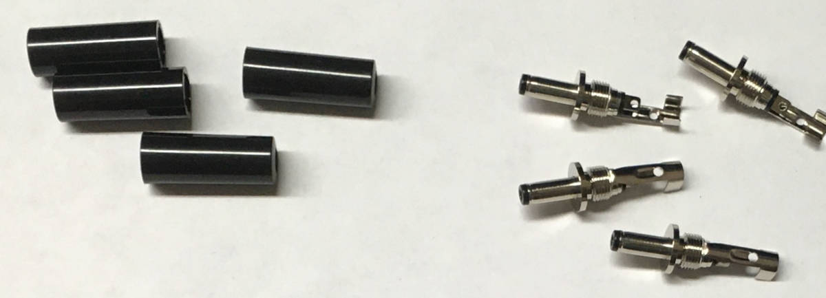
For each cable you will need one large barrel plug,
one small barrel plug, consisting of the plug (on the right side) and the holder (left side),
one large and two smaller heat shrinking tubes,
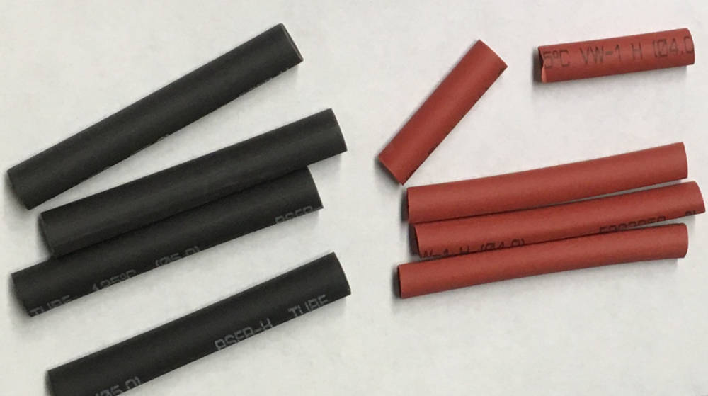
and some wire:
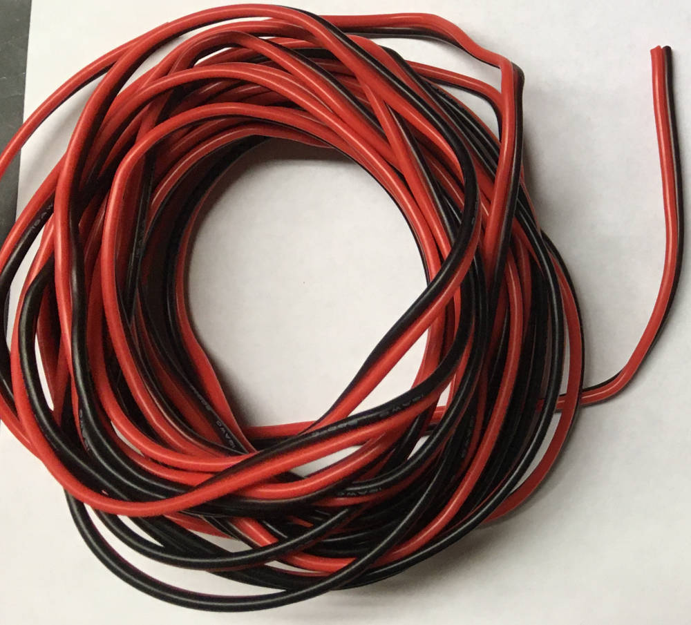
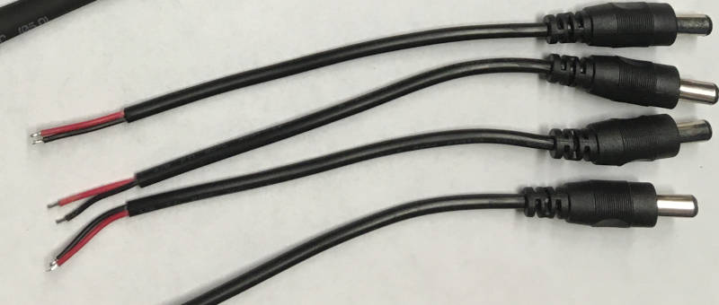
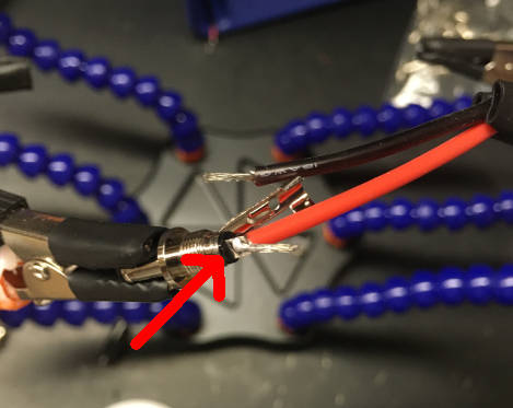
Cut ~50 cm (or however long you want the wire to be). Take the 3.5mm barrel connector and place the red wire into the center hole of the connector. Place the black wire into the hole on the side of the connector.
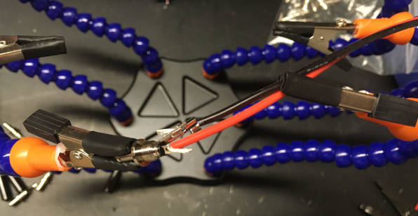
Solder the red wire to the 3.5mm barrel connector. If there is a lot of leftover wire as in the image below, it is a good idea to cut it away.
Now solder the black wire to the 3.5mm barrel connector. Again, make sure to remove leftover wire.
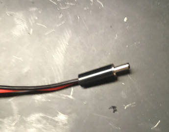
Finally, thread the cylindrical black plastic screw on top of the just soldered 3.5mm barrel connector.
After screwing the back onto the barrel connector, it should look like this:
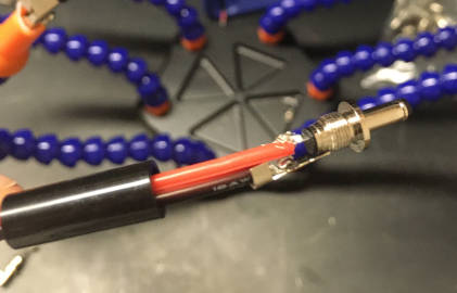
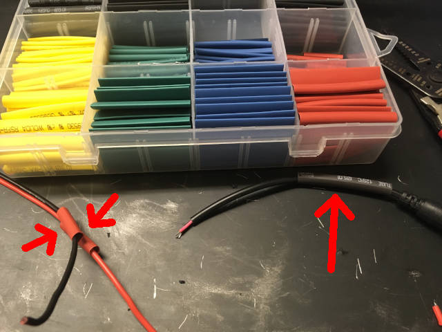
On the opposite side of the cable, start by placing the heat shrink tubes as indicated below: One small set of tubes on each of the thinner wires (left arrows) and one larger one on the male large barrel plug (right arrow).
Solder the red wire of the large barrel connector to the (+) wire. In our example that would be red wire.
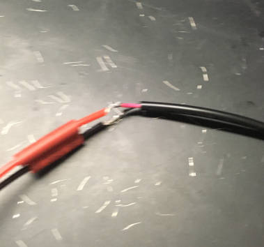
Using a heat source, use the heat shrink tubing to stablize the cable: Start with the thinner wires and finally push the larger heat shrink tube over the other two.
1.4.2. Troubleshooting LEDs
If you can not turn the LED on using PiVR, the first test should be whether there is an error in soldering the LEDs. To test this, plug the 12V wall adaptor directly into the LEDs on the illumination plate.
If the LEDs do not turn on, it is very likely you have a loose connection on the illumination pad. Carefully check each solder patch . It is also possible you mixed up (+) and (-) somehwere. Finally, it is possible that you wall adaptor is broken, however, this never happened to me.
If the LEDs do turn on when you connect the 12V wall adaptor directly to the LED, there are several options what could be going wrong: (1) The cable might have a faulty connection. (2) The PCB board might have a faulty soldering connection.
To address (1), you can use the ‘resistance’ option on your voltmeter to check if the two ends of the cable are electrically connected. If you read ‘0’ (or a very small number), the cable is good.
To address (2), you will have to take out the PCB of the PiVR setup again. Carefully inspect the soldering. Make sure everything that can be soldered is soldered and that no two solder patches touch each other. If that checks out good, double check if you soldered the GPIO header onto the board the correct way.
If you are still not getting any light out of the LEDs, feel free to submit at ticket on the PiVR repository