PiVR has been developed by David Tadres and Matthieu Louis (Louis Lab).
11. PiVR Benchmark
11.1. Concepts
When creating a virtual reality two different measurements of time are relevant:
The loop time: How often per second does the system take input from the subject? This is usually expressed in Hz.
The latency: How long between taking the input and presenting the subject with the updated stimulus that makes the virtual reality? This is usually expressed in milliseconds (ms).
Next, how can one measure time on a computer? Most operating systems (Windows, MacOS and Linux) are non-real time operating systems. This means that the OS can not guarantee that a given line of code is executed at a fixed interval. If one asks the system to simply record the time to measure loop time and latency on introduces uncertainty, possibly in the order of milliseconds.
Luckily PiVR has a real-time operating system - on the GPU: Digital cameras work by reading out lines on their sensor and the camera used by PiVR is no different. (Read here for a fantastic introduction).
For example at 90 frames per second at 640x480 the camera must read out 480 lines in ~11ms. It must therefore spend no more than 2.3^-5s or 23.1us per line. This means every 23.1us the camera is pushing one frame line to the GPU (see here for detailed information).
The GPU records the timestamp of when the first line of a new frame is received based on its real-time hardware clock. We take advantage of this while doing the PiVR measurements. This timestamp is called presentation timestamps (PTS). (More info here).
11.2. PiVR loop time
PiVR loop time has been tested by recording the PTS while doing real-time tracking at 640x480 resolution and a variety of framerates using a Raspberry Pi 3.
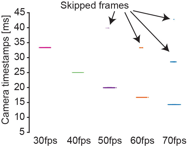
For example at 30fps each camera timestamp should be 1/30 = 0.033s which of course is 33ms. The reported timestamps are perfect for 30 and 40fps. At 50, 60 and 70fps we start loosing a few frames (6/5,598, 25/7,198 and 16/8,398, respectively) meaning PiVR could not keep up with the images coming in therefore the loop time was larger than 1/fps.
For more detail please see Timing Performance of PiVR
11.3. PiVR latency
To measure latency we turned the LED on at a defined frame and asked how long it takes for PiVR to detect the change in light intensity.
This was based on the excellent suggestion of Reviewer #1:
Run closed loop tracking at 70fps at 640x480 with a facsimile larva.
At each 50th frame of a trial (and multiples thereof), turn the red LED on.
Take the median of a set of 10 pixels in the search box and compare the average current intensity to the intensity of the previous frame.
If this difference is larger than 2, consider the LED “ON” and immediately turn the LED “OFF”.
If the LED has been turned “OFF”in the previous frame, turn the LED “ON”again.
The code used for this can be found on the Gitlab repository of PiVR Gitlab repository of PiVR in branch ‘LED_flash_test’ in the file ‘fast_tracking.py’ with relevant code going from line 1457 to 1584.
Using the methodology described above, we found that the detection of a ‘LED ON’ event was either detected during the earliest possible frame or one frame later. This difference in latency was dependent on the region of the image (region of interest, ROI) used to compare the pixel intensity. The detection latency was systematically longer when the ROI was in the top (green box) as compared to the bottom of the image (magenta box).
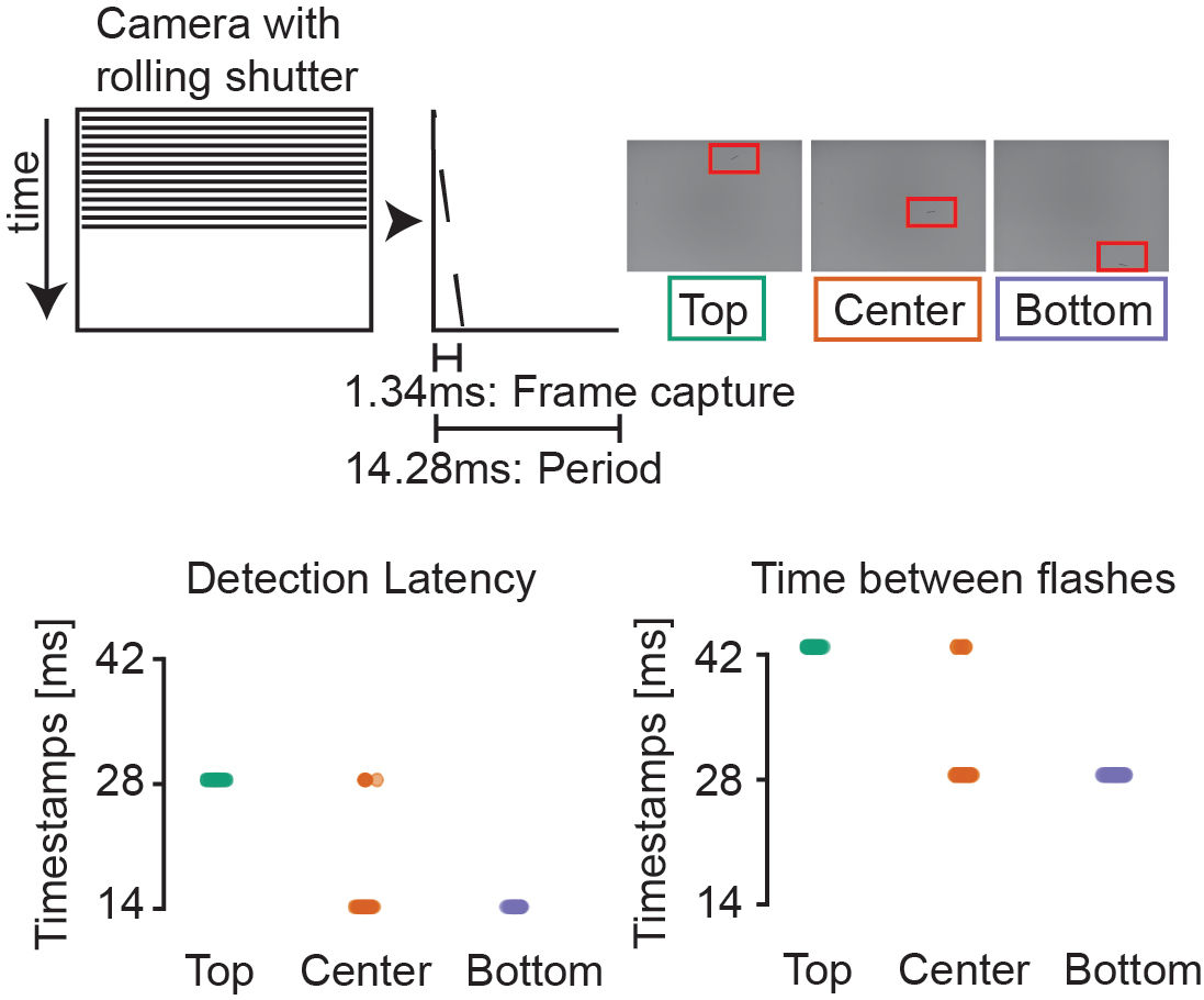
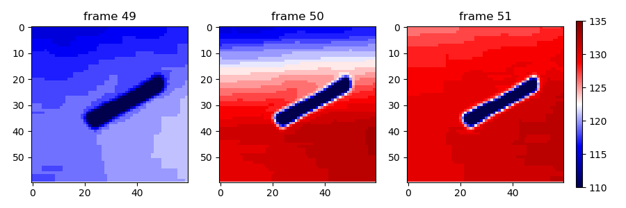
As illustrated in the figure below, this can be explained by the fact that turning the LED “ON” while the camera is grabbing the frame through the rolling shutter cannot lead to a successful detection of the change in light intensity. During frame #50 the LED is still “OFF” in the top part of the image whereas it is “ON” in the lower part of the image.
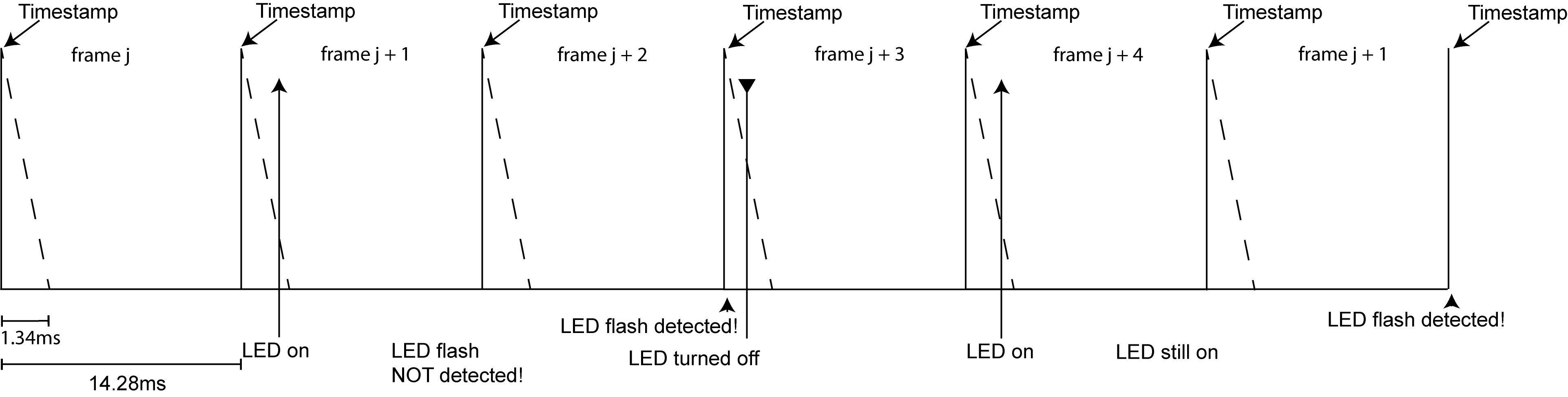
As shown above the number of frames between two consecutive events corresponding to the LED being turned “ON” was 3 frames if the ROI was located in the top part of the image (green box). The schematic diagram below outlines our interpretation of this 3-frame delay: The LED is being turned “ON” during frame (j) while the frame is being recorded (vertical arrow in frame j + 1). If the PiVR algorithm is set to monitor a ROI in the upper part of the image, this ROI is read before the LED intensity has switched to the “ON” state. Therefore, the LED “ON”event is not observed during frame j. Instead, it is detected during processing of frame j + 1. This delay happens again when the second LED “ON” event is detected in frame j + 4.
By contrast, if PiVR is set to monitor a ROI in the lower part of the image, the LED turn “ON” event can be detected while processing frame j + 1 (see below).
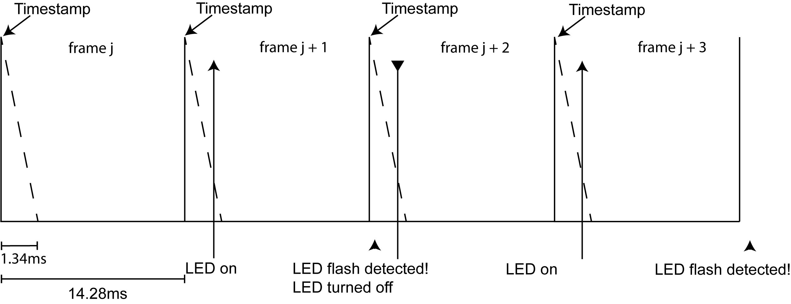
Consequently, the time that elapses between the two LED “ON” events is either 5 frames (or 71ms at 70 Hz) for a ROI in the top part of the image or 2 frames for a ROI in the bottom part of the image.
Based on these observations, we conclude that the LED “ON” event must be happening while the image is being captured, which corresponds to a duration of 1.34ms. The longest possible latency between the action of an animal (in this example during frame j) and the actuation of the update of the LED is therefore 2 frames + 1.34ms (time window associated with frame j + 2), which is equivalent to less than 30 ms (frame duration at 70 Hz is 14.29 ms.
11.4. PiVR loop time (High Res)
PiVR v1.5.0 was released on 27th of March, 2021. It allows users to perform online tracking with resolutions other than 640x480.
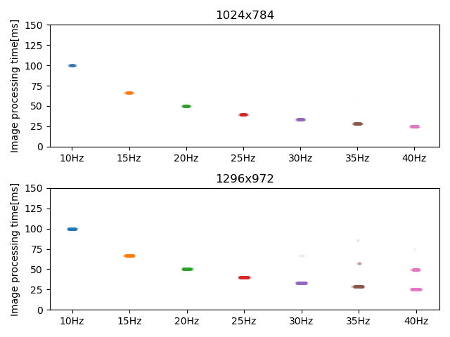
Higher resolutions impact the closed loop times as a larger image is being analyzed to define the animal in each frame.
We tested the performance using both a Raspberry Pi 3 Model B Plus Rev 1.3 and the newer and more powerful Raspberry Pi 4 Model B Rev 1.2
The Raspberry Pi 3 was able to handle 30fps without dropping frames at 1024x768. At 1296x972 it was only able to handle 15fps without dropping frames.
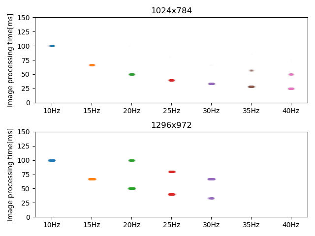
The 50% more powerful Raspberry Pi 4 on the other hand was able to handle 40fps at 1024x768 and 30fps at 1296x972: